What is my project?
Research Question
How can we make data interesting?
The primary objective of this project is to make data visually interesting, as simply staring at numbers has become monotonous. By presenting the data in a tangible form, it encourages viewers to contemplate the significance of those numbers.
What is the importance of this project and why sleep data?
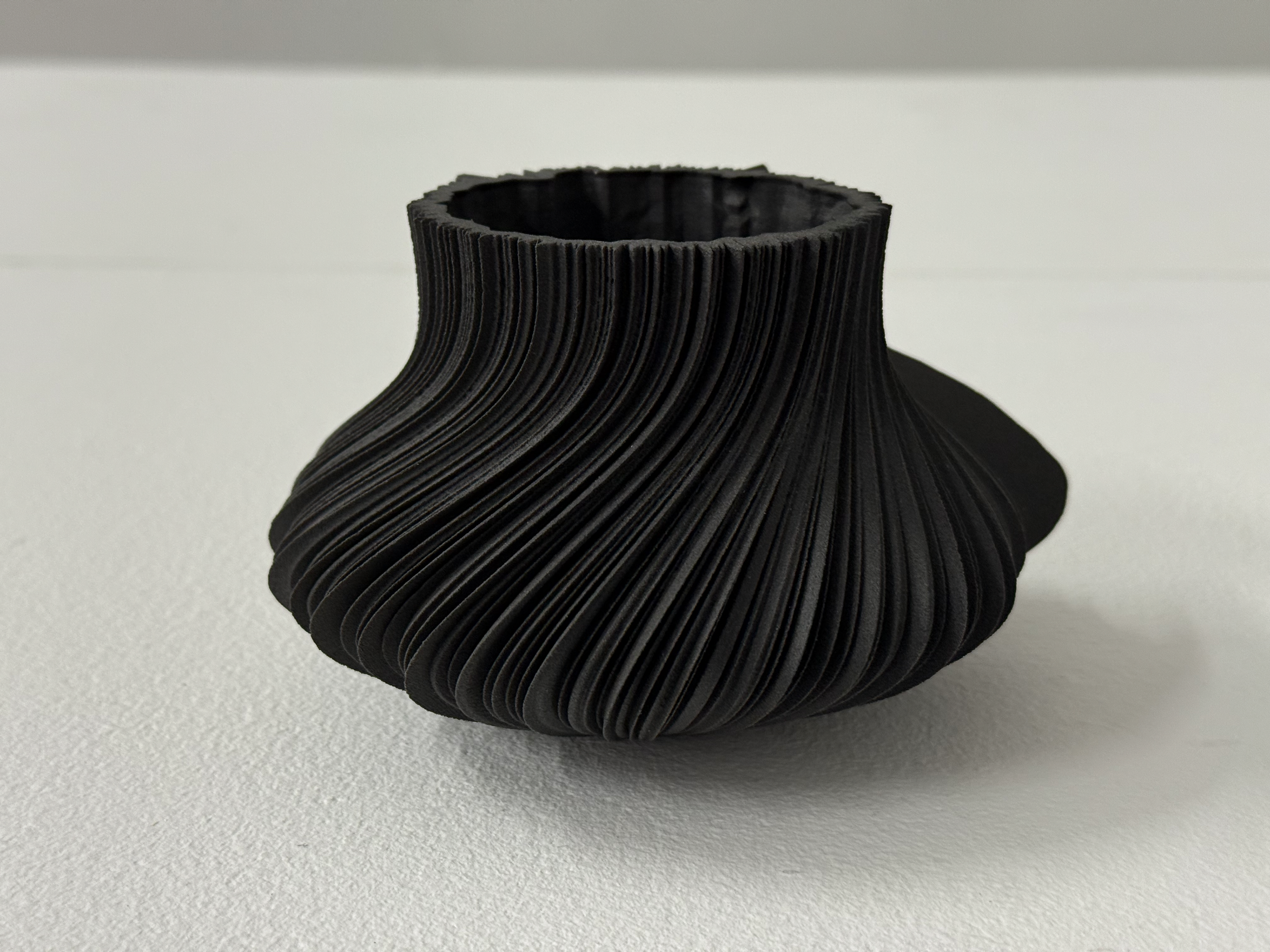
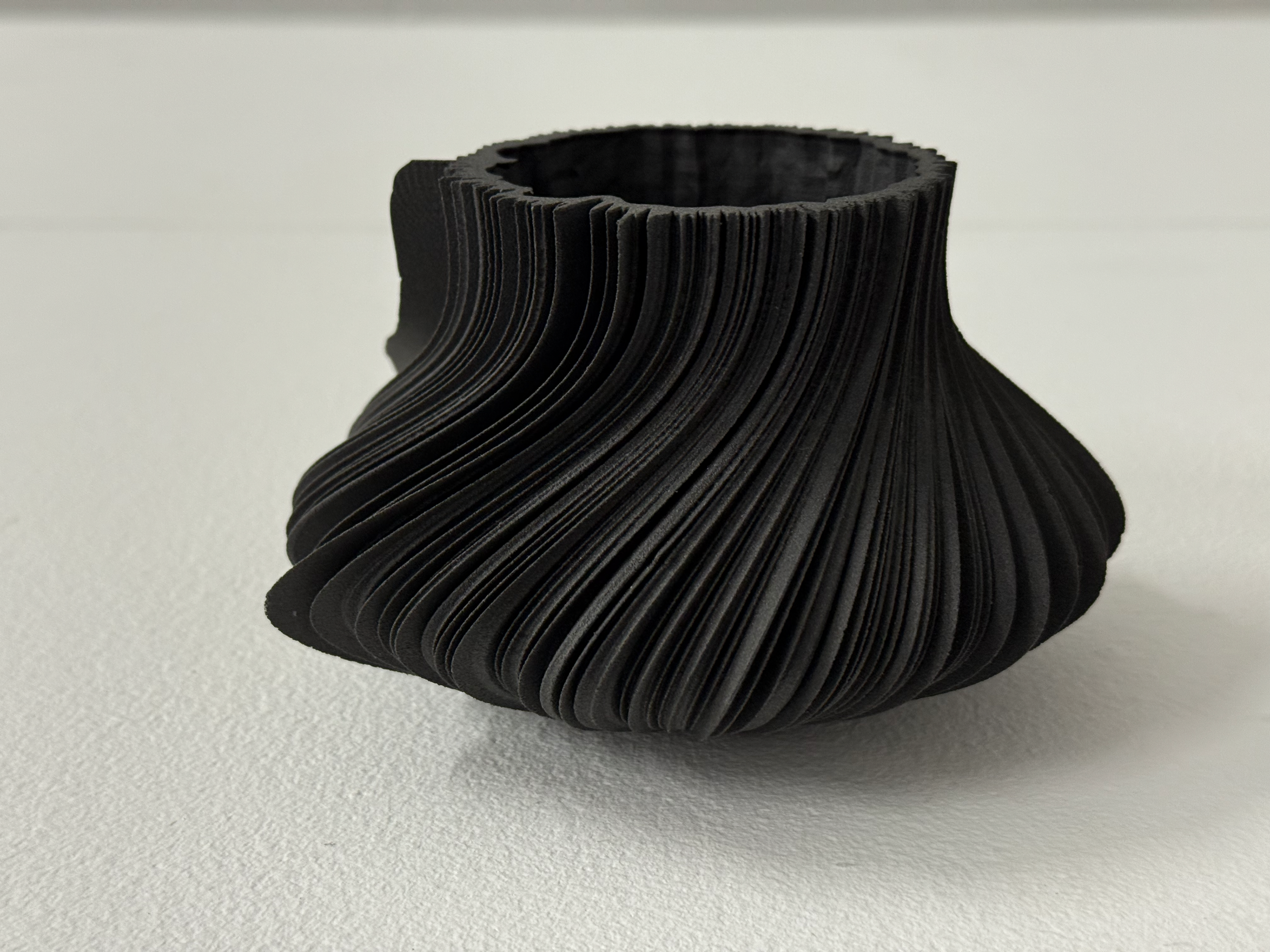
I wanted to answer my research question with resources that I have access to myself, leading me to use my Whoop data. I selected Sleep because it is the only aspect that is repeated and drastically different every single day. The use of average heart rate over the course of the data set is a representation of overall health. When combined with a single night’s sleep, it's a representation of our health at that time. By showing multiple versions side by side, you can clearly see the difference sleep has on us, turning boring numbers into an interesting real-world form.
Final Day Selection
My Data
Day 72 (29th July 2023)
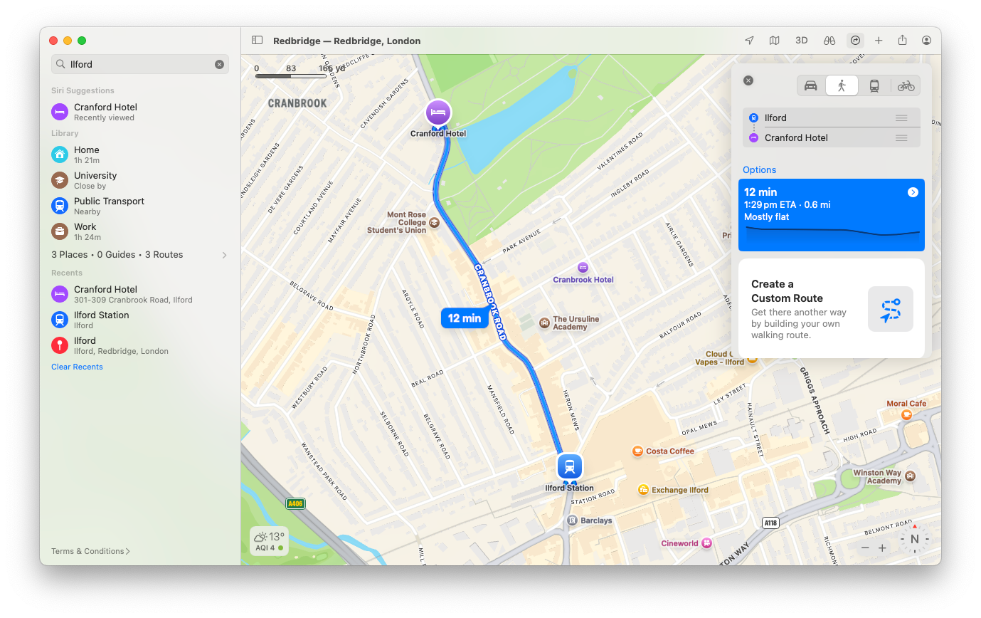
This data is taken between 22:36:21 on the 28th of July 2023 until 08:57:22 on the 29th of July 2023. I didn't journal at this time, so I am unsure of what factors caused this, but from my calendar, I can see I had travelled down to London on the train departing at 13:40 from Lancaster, arriving at London Euston at 16:12, followed by a 31-minute tube journey to Ilford, and finally a 12-minute walk to the hotel.
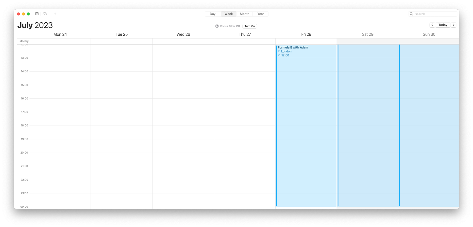
Calendar Event
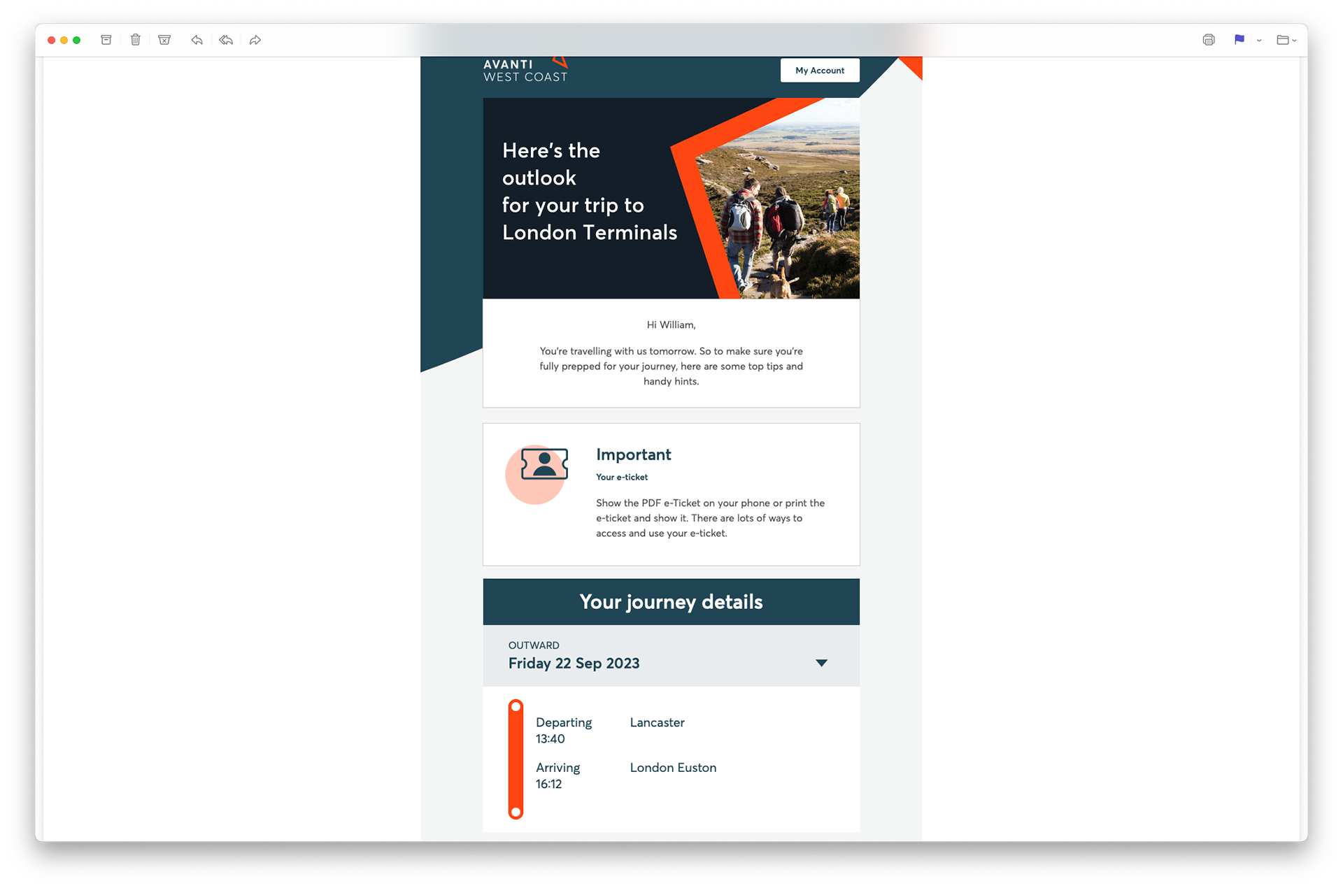
Email with the train time on
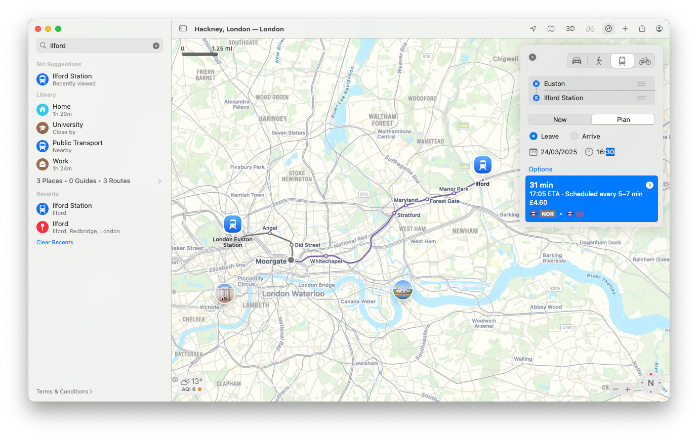
The route I would have taken
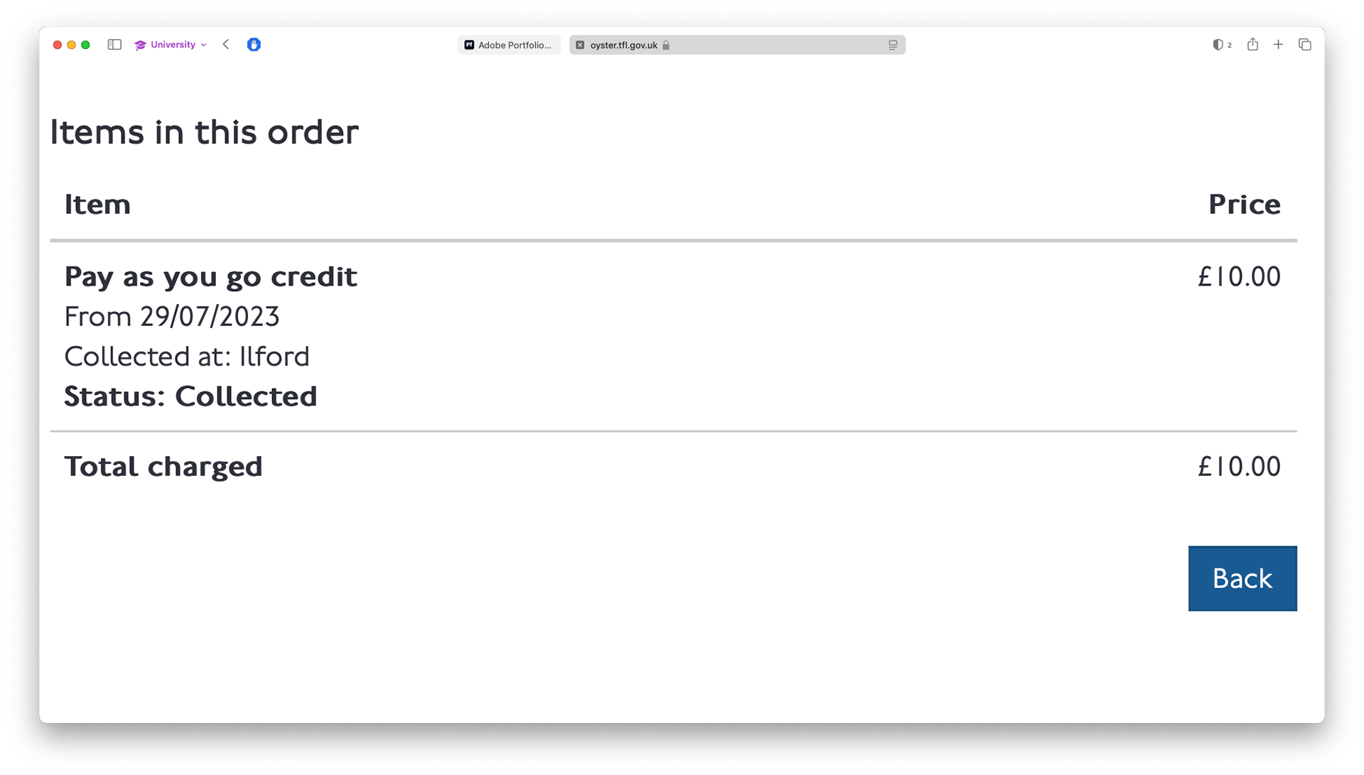
The Oyster card top up receipt told me where I stayed
From the station I could find the hotel I stayed at
Since this project is data-driven, I think it's important to include as much data as I can to give context to what has formed my sleep and, as a result, my object.
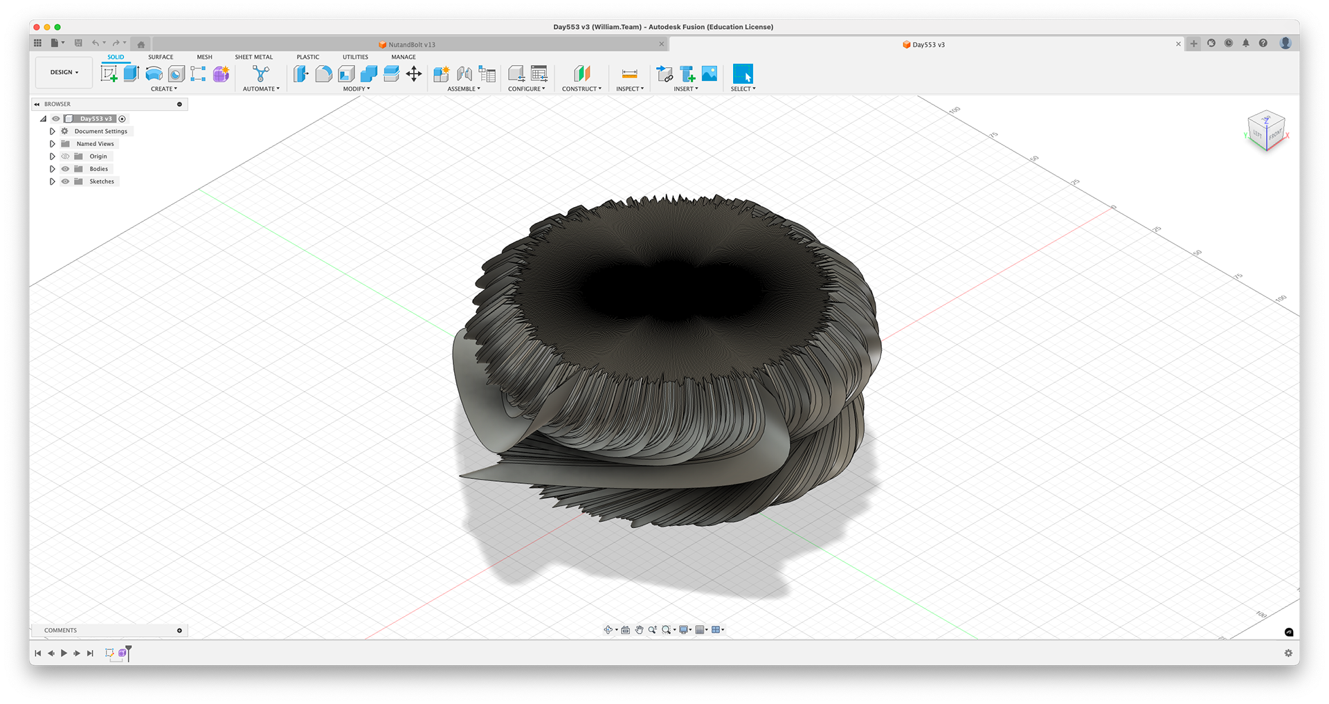
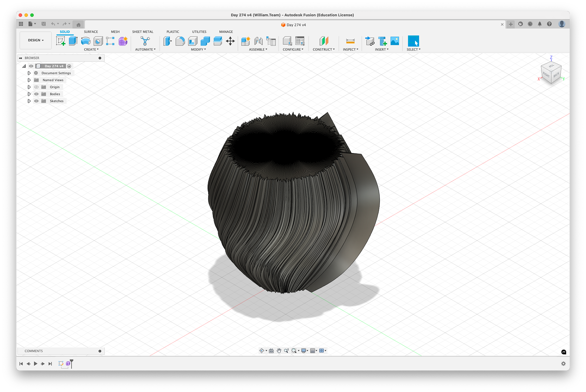
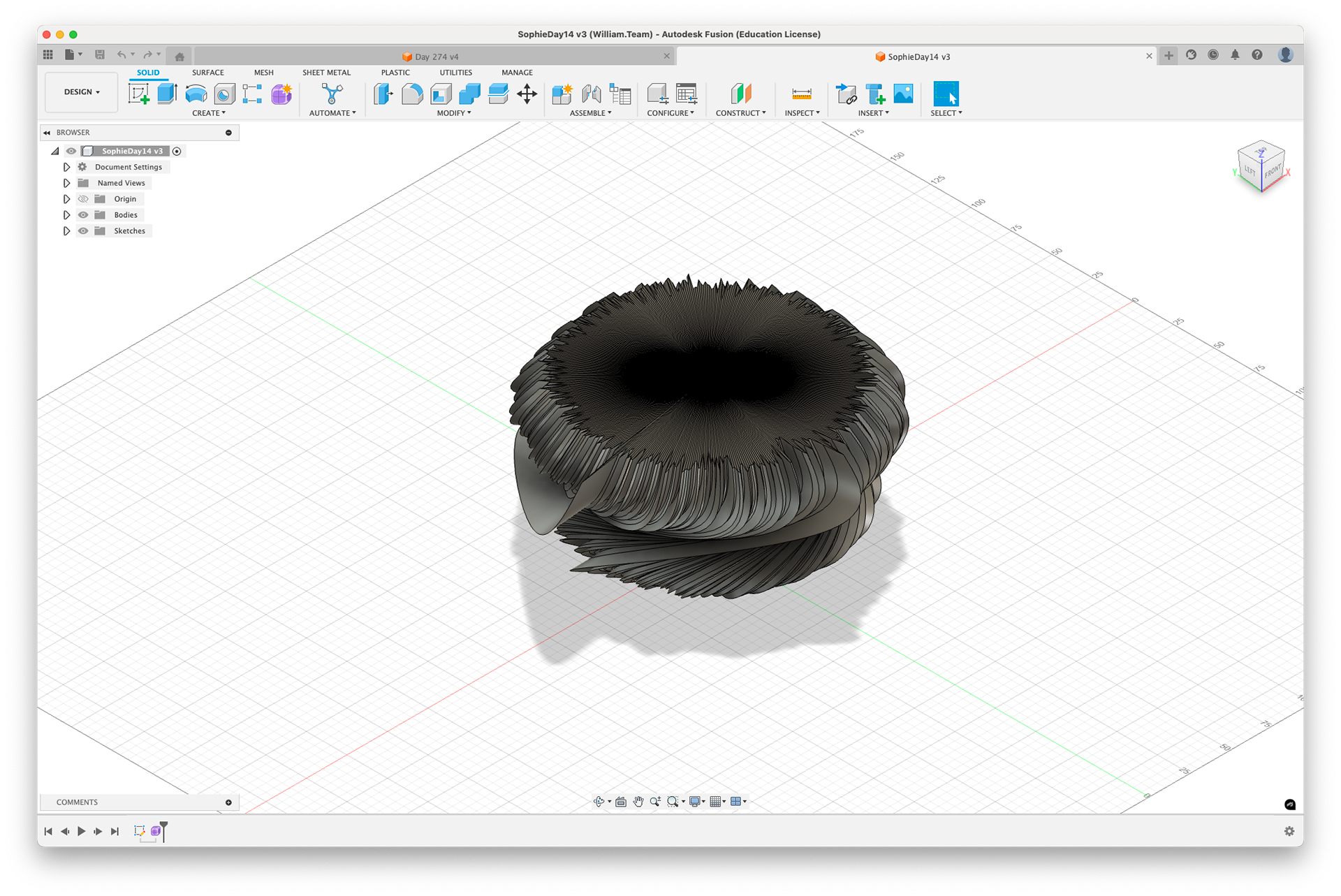
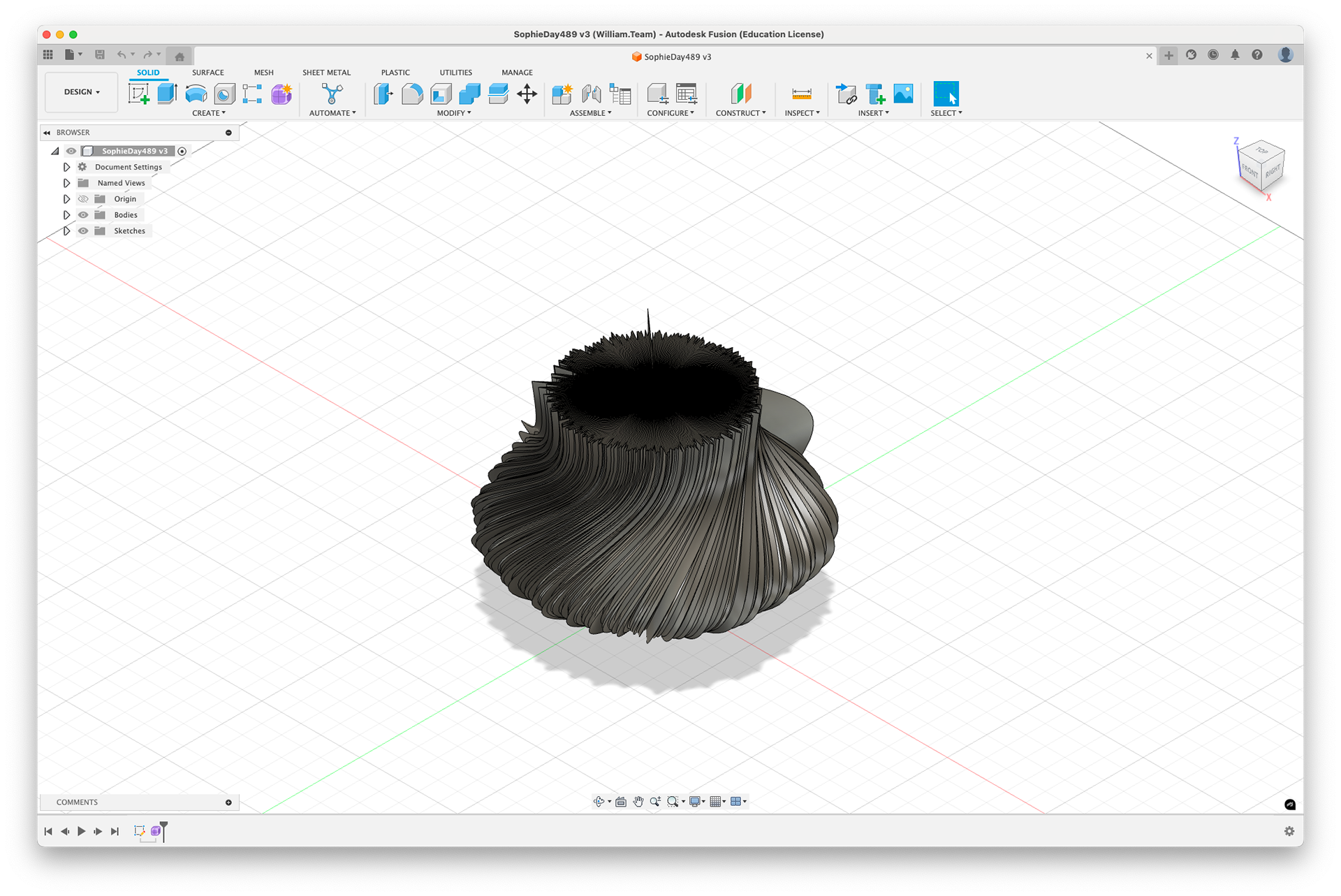
The model in Fusion 360 - due to limitations, I am unable to hollow this object; this is done within the FormLabs PreForm App.
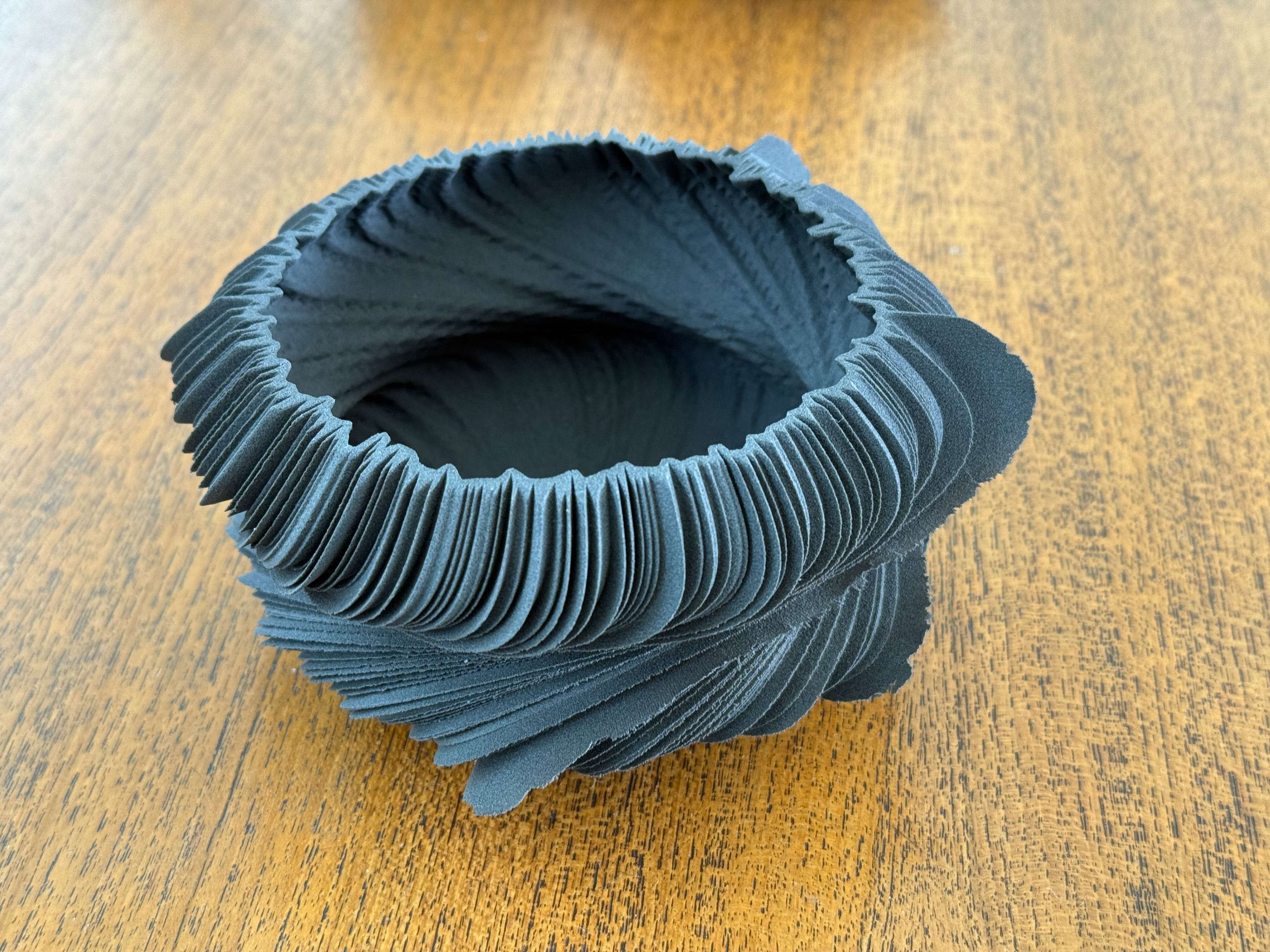
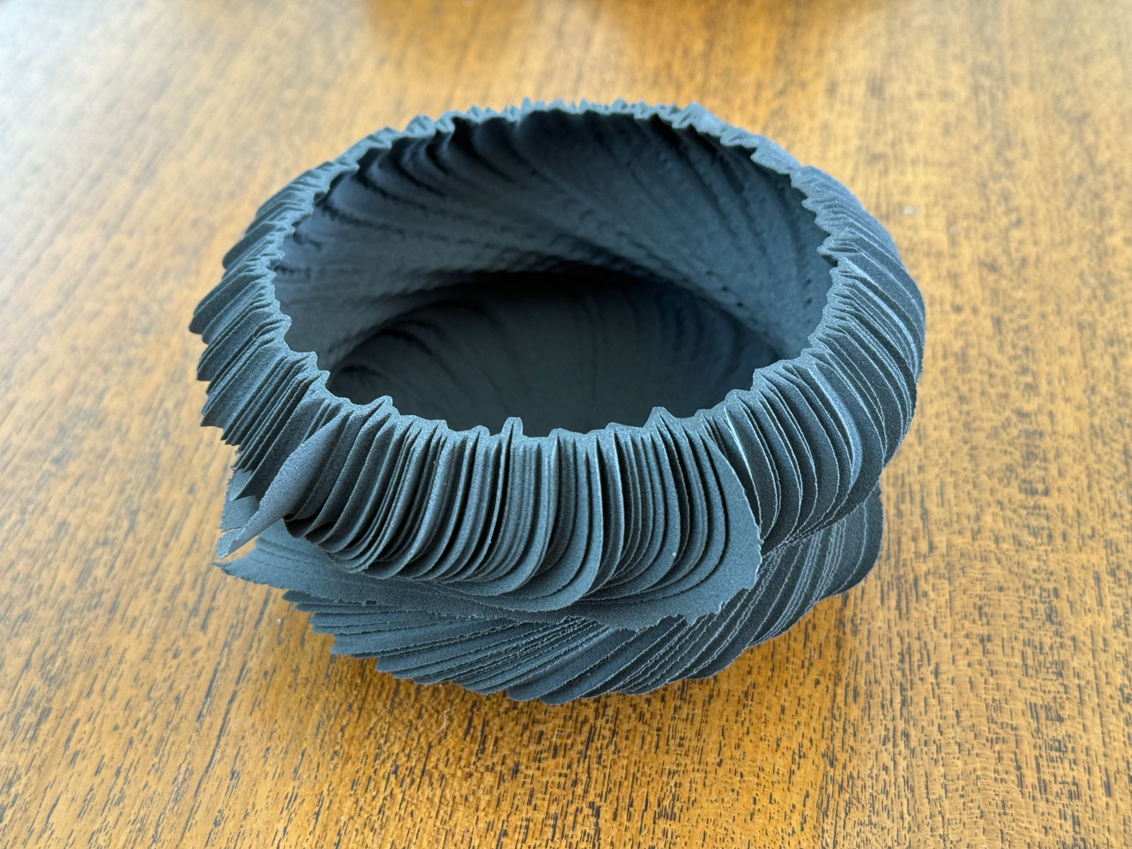
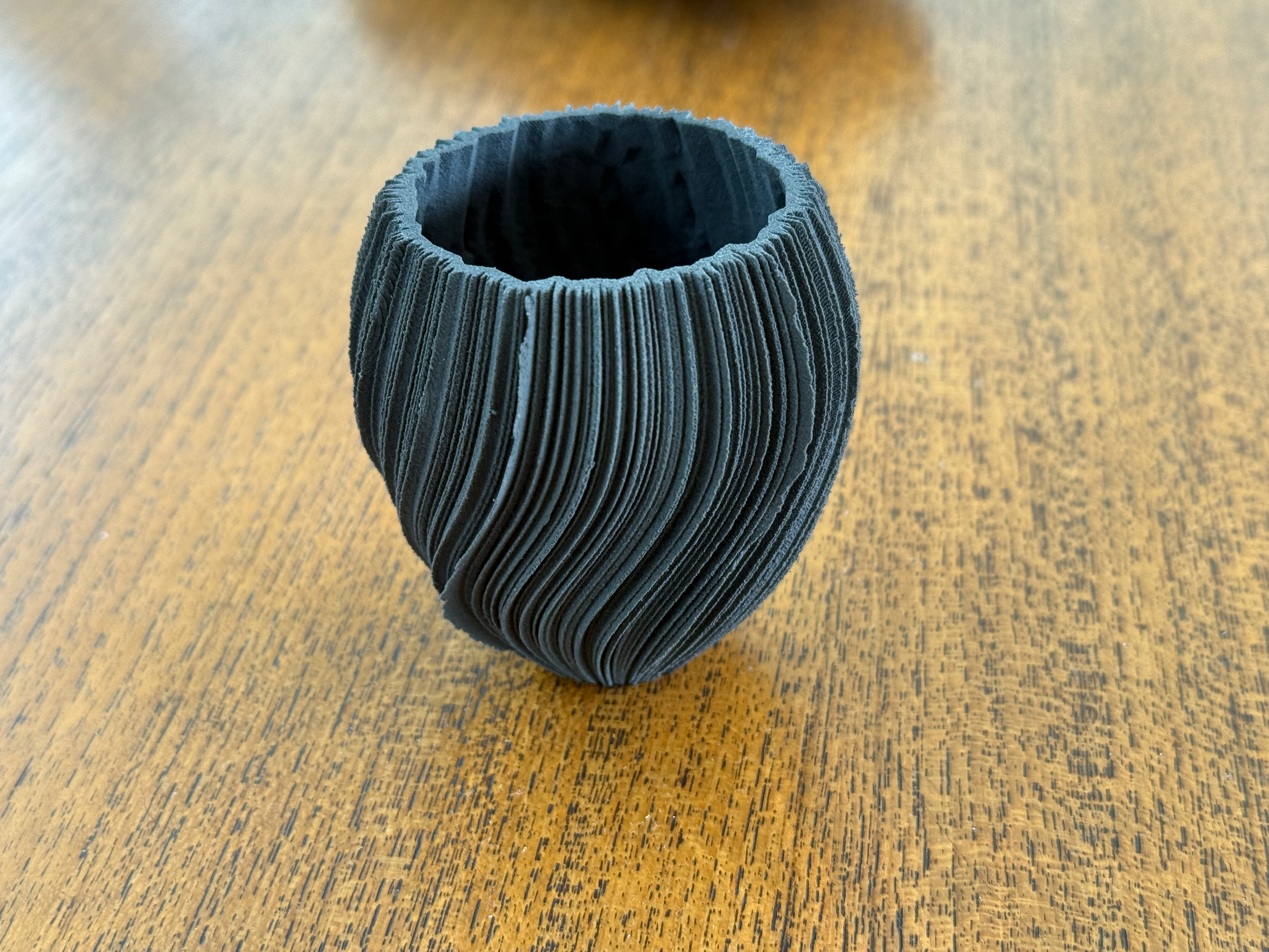
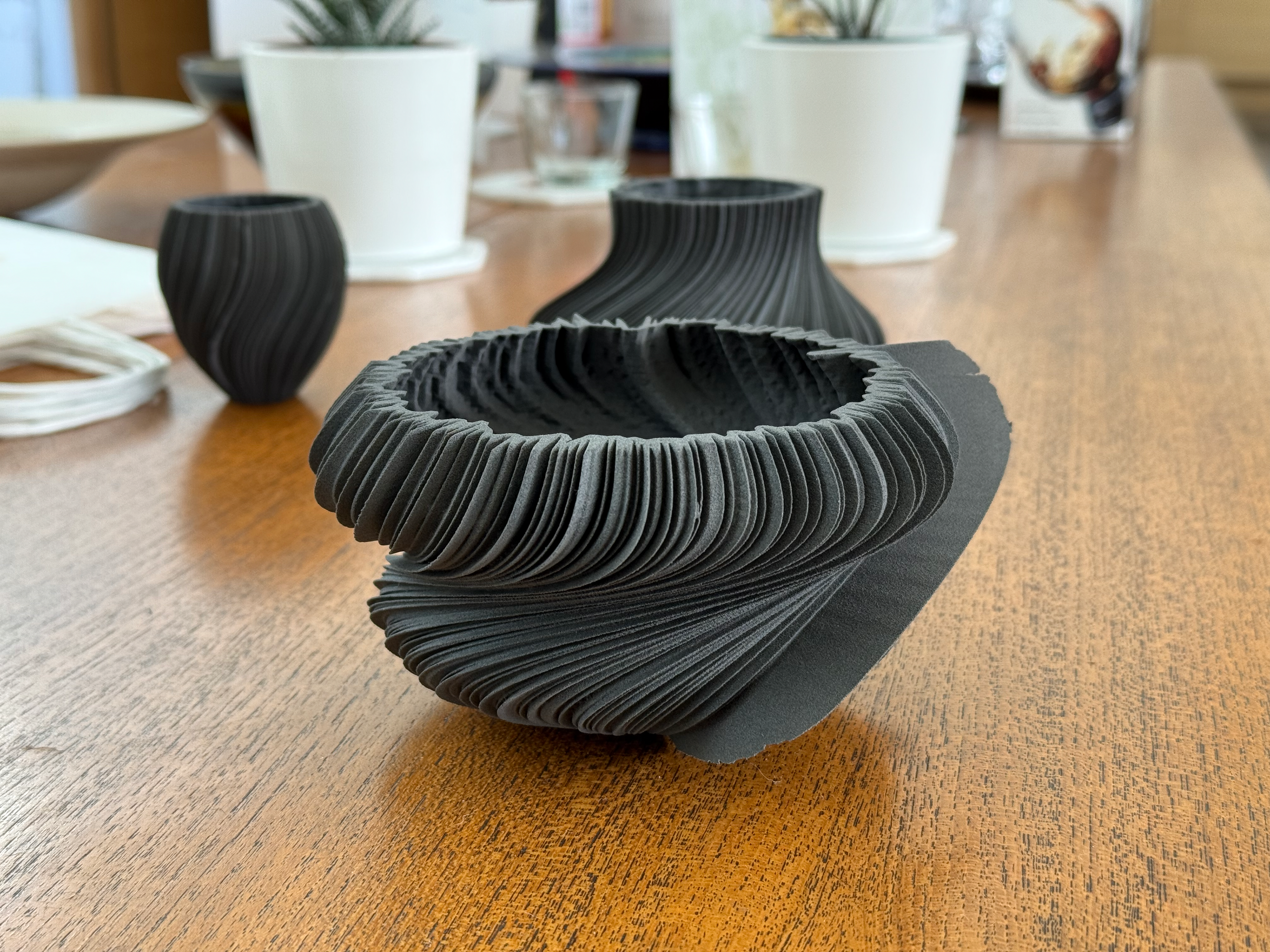
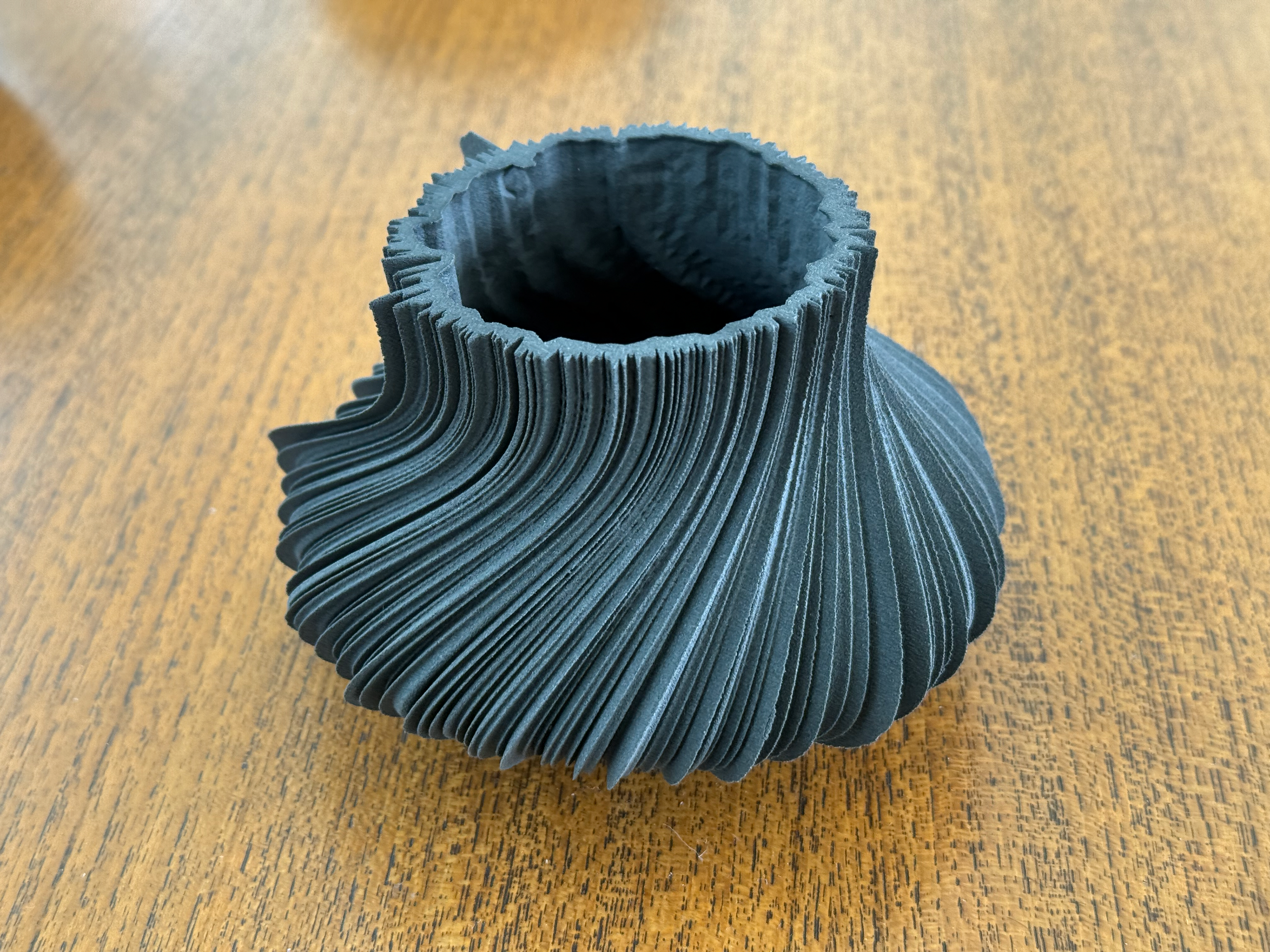
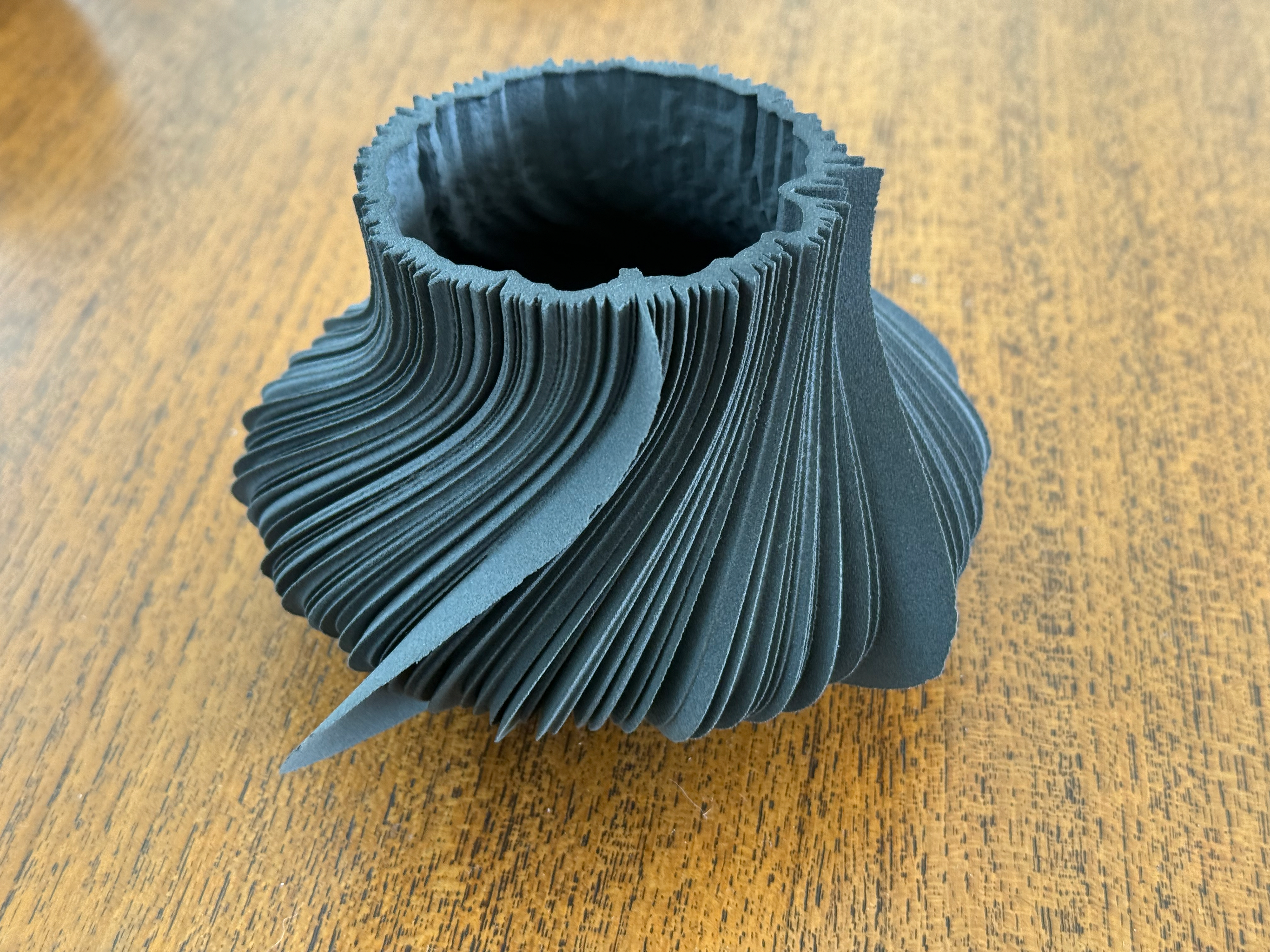
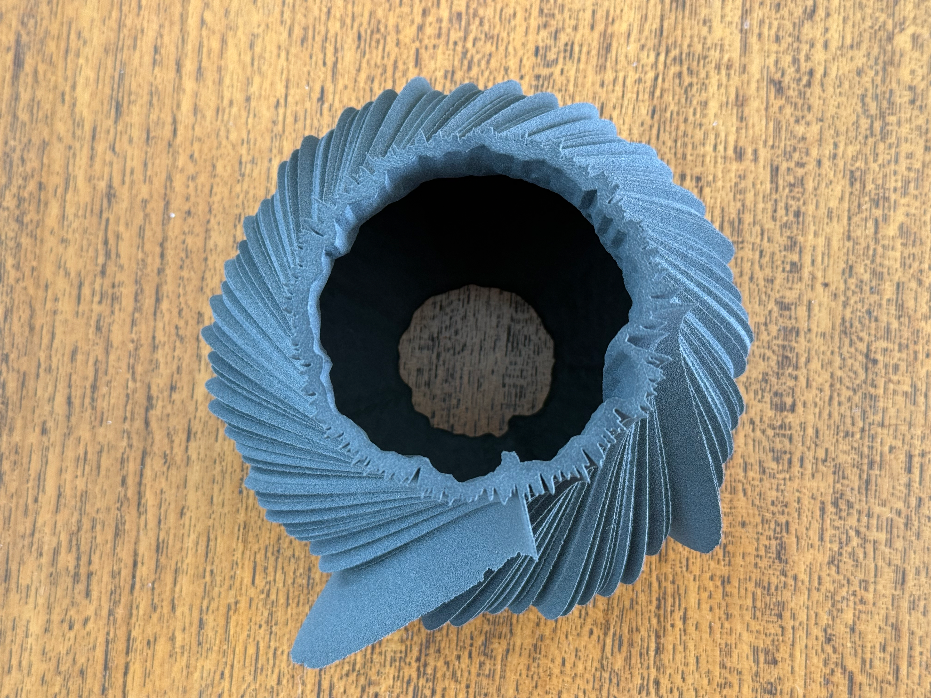
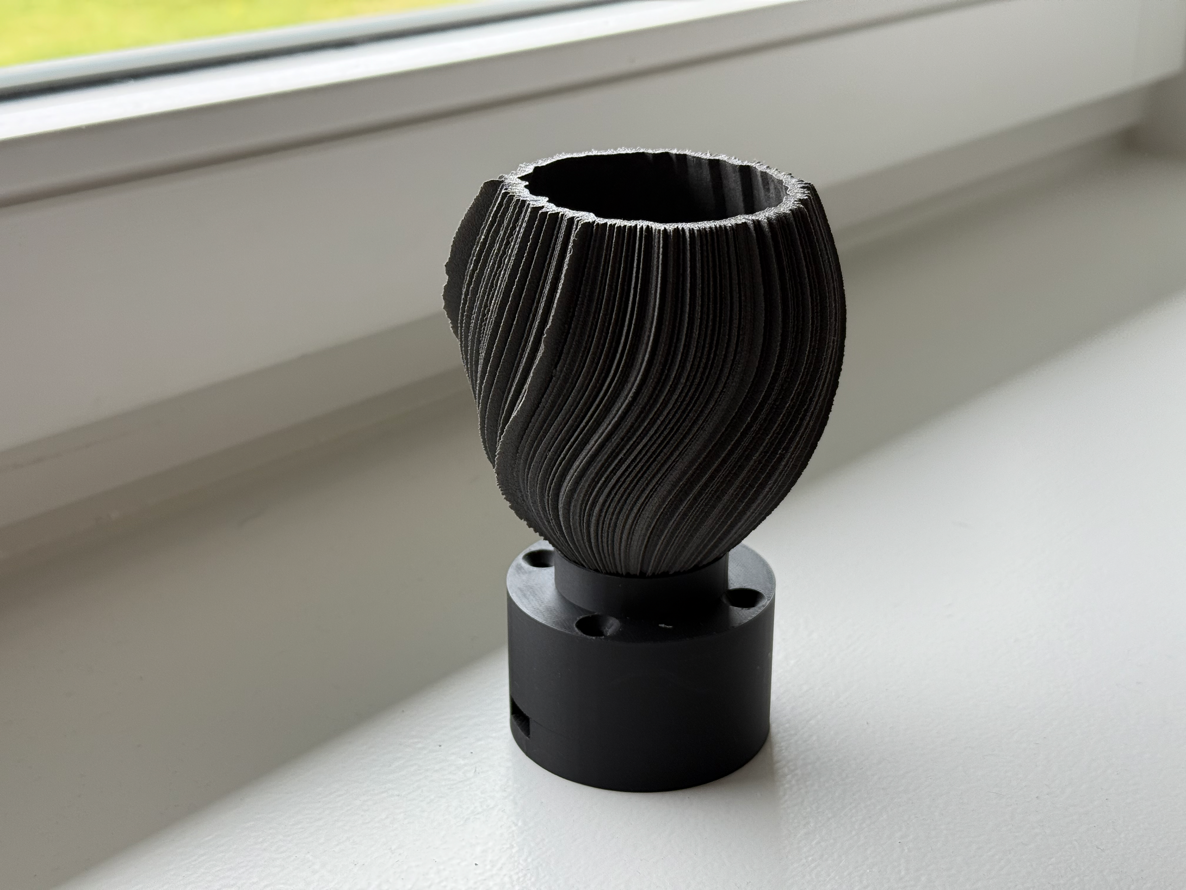
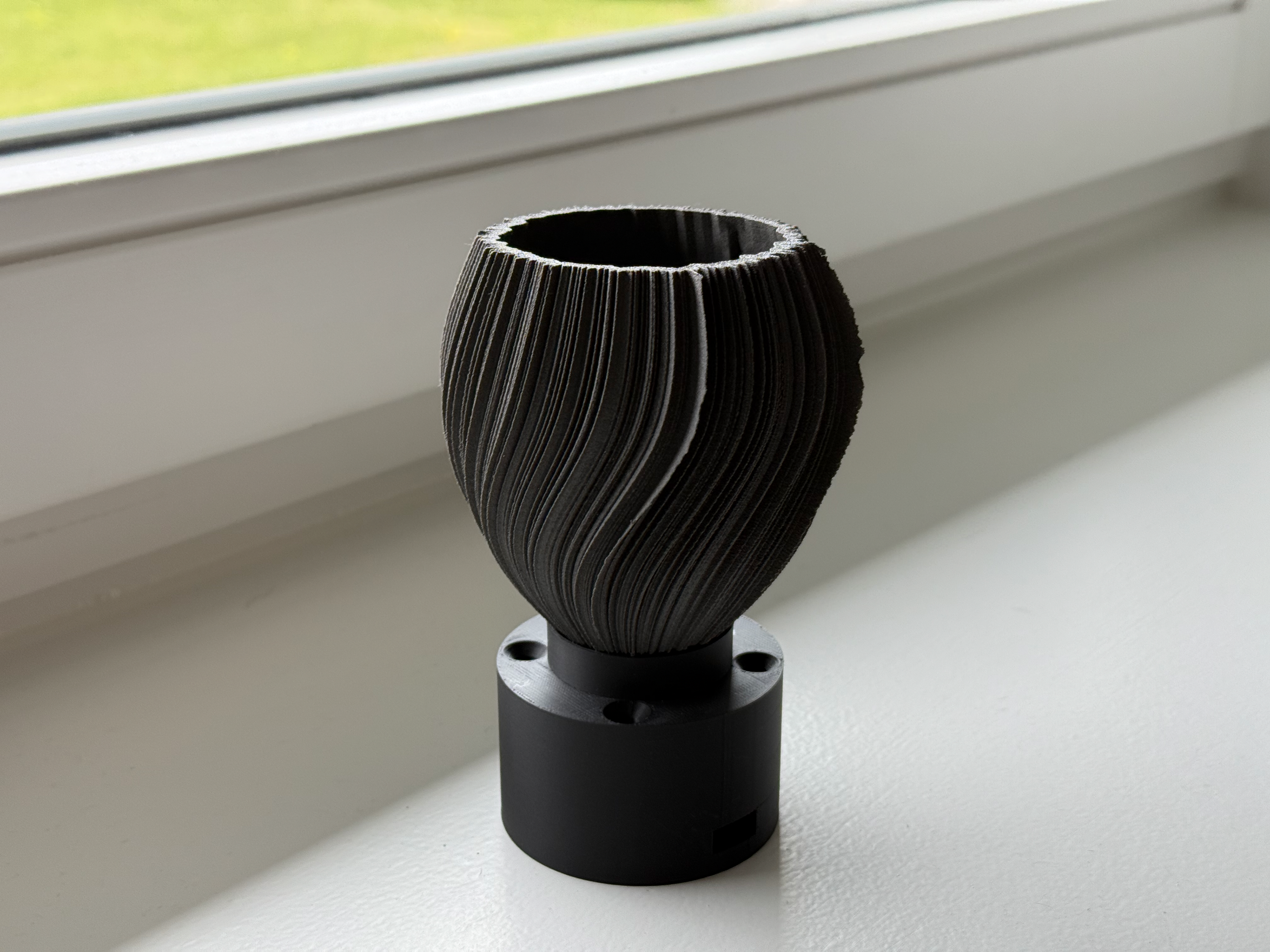
Final material print.
Day 351 (4th May 2024)
By this time, I had started journaling. From my journal, I can see that I went out for drinks and stayed out, going to sleep at 6:18, and waking up at 10:32.
The model in Fusion 360.
Final material print.
My Cousins Data
Since this is my cousin’s data, I need to be quite sensitive about what information is publicly displayed. Although this is anonymous, I want to keep sensitive information out.
The inclusion of my cousin’s data is to give a comparison between myself and an athlete. My cousin is an athlete competing in swimming at national levels. By comparing myself to someone else, it should give the viewer some context on how an "average" person is different from an "athlete" and how data really is different, particularly sleep between people.
Day 498 (3rd february 2025)
The model in Fusion 360.
Final material print.
Day 23 (23rd november 2023)
The model in Fusion 360.
Final material print.
Mounting
Display
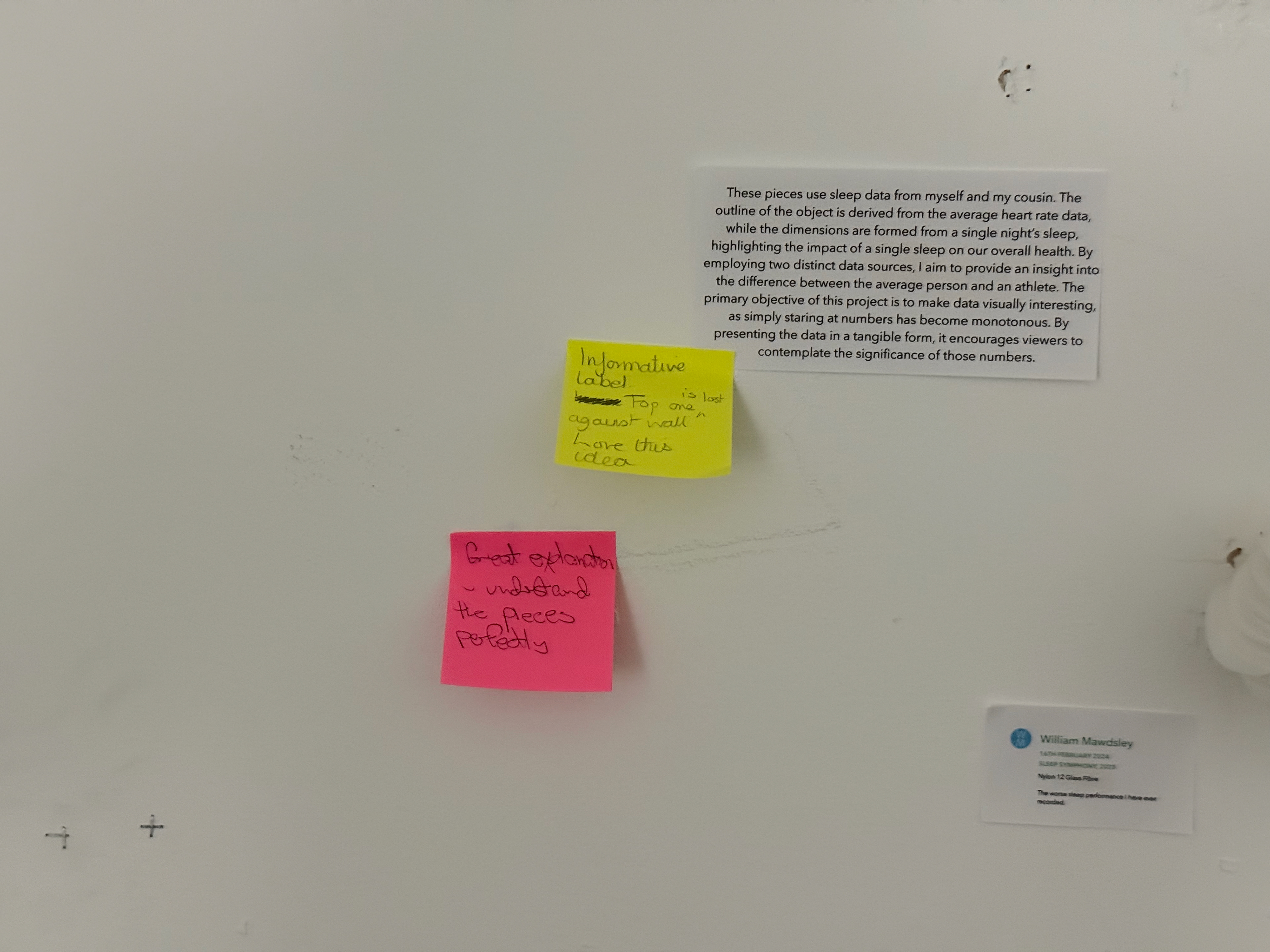
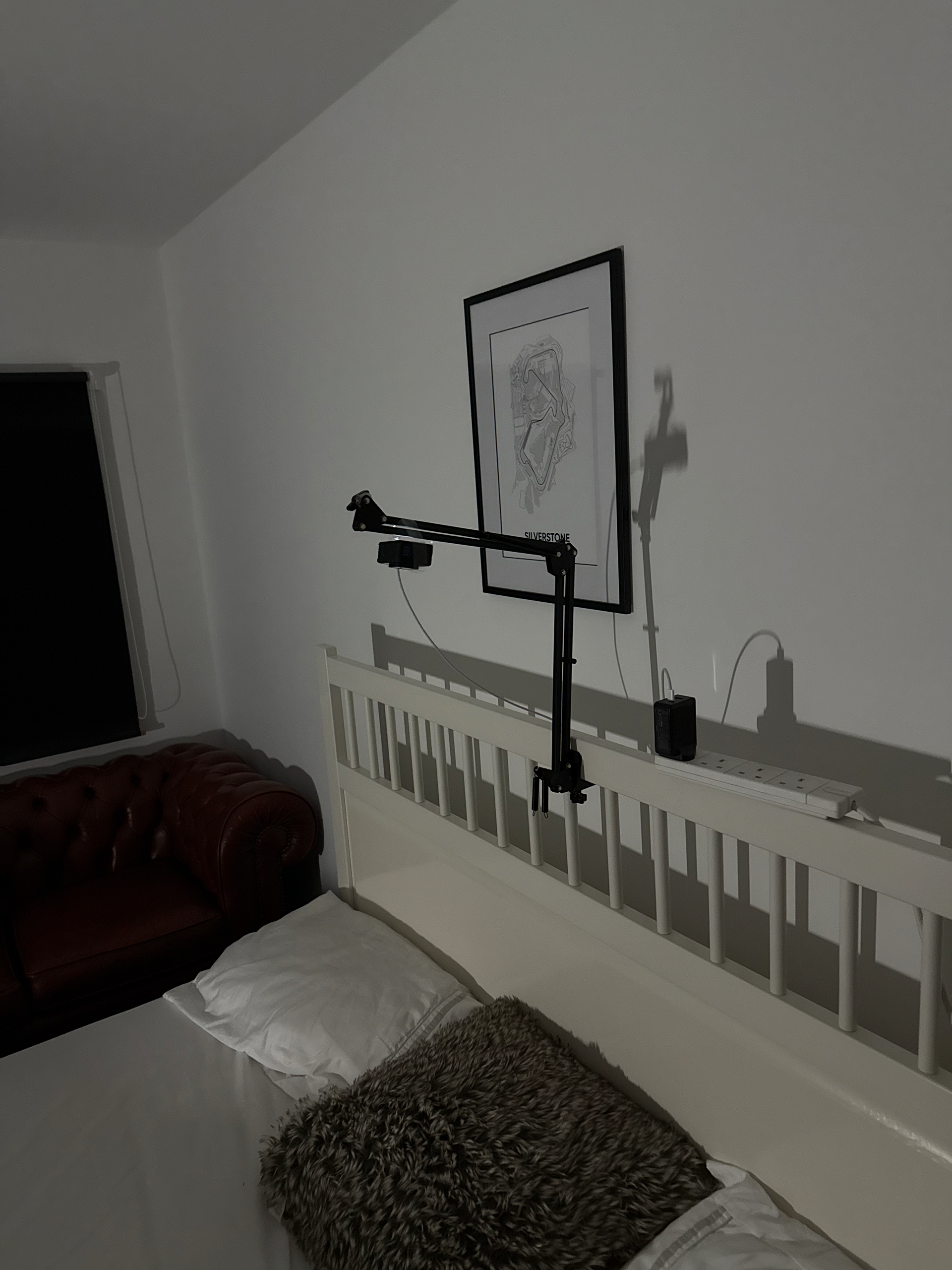
We were asked to do a mock-up of our curation ideas. Since I didn't have my final pieces, I used development pieces that were roughly the correct size and experimented with some basic labelling. Overall, it was a success. I would like to space out the objects further and use lighting to bring the viewer’s attention to them. But mounting on the wall at eye level will be the way forward. I would like to try and bring the viewer’s attention to the side of the objects because that is where the interesting part is.
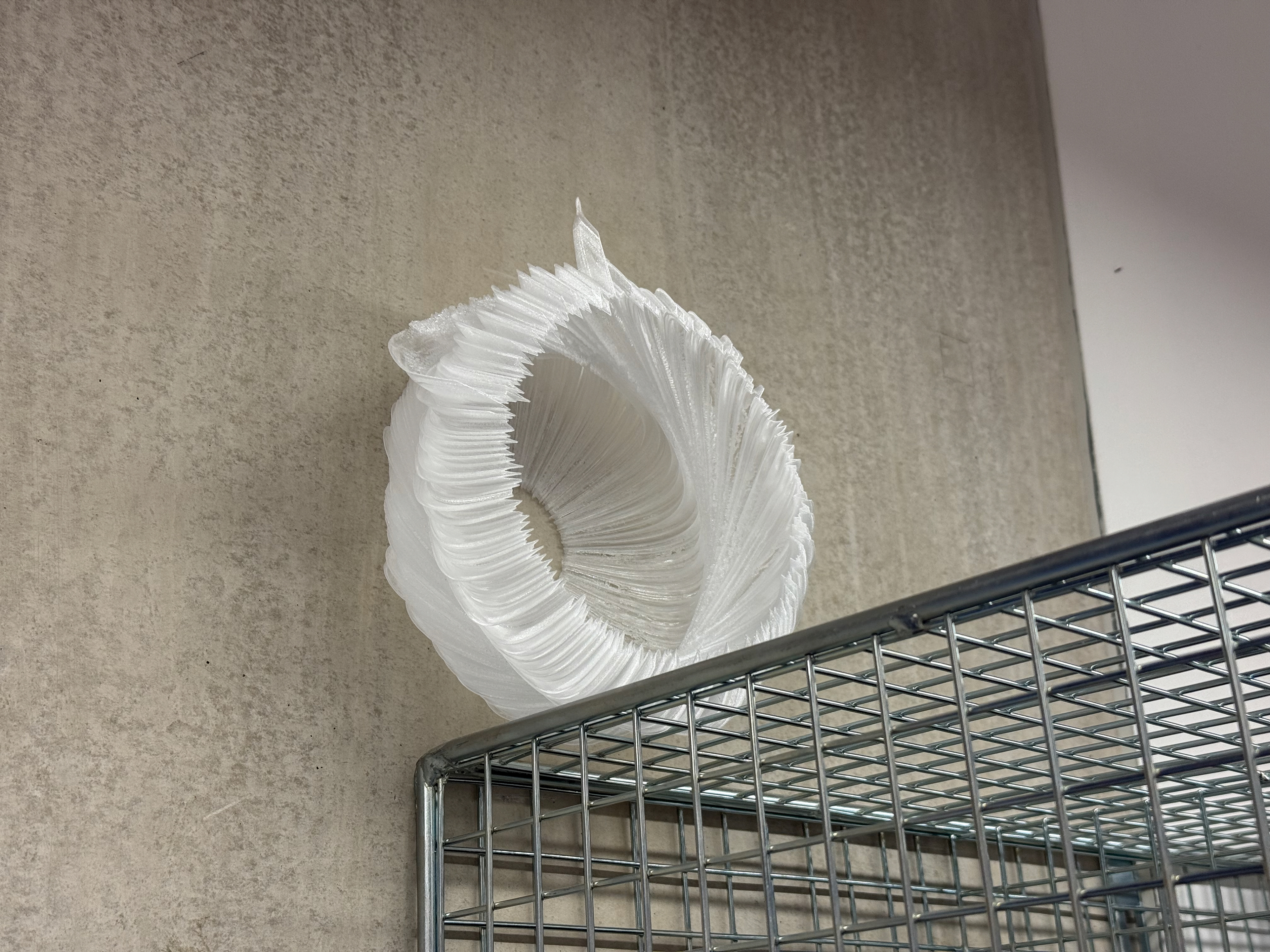
Pre mock up against concrete
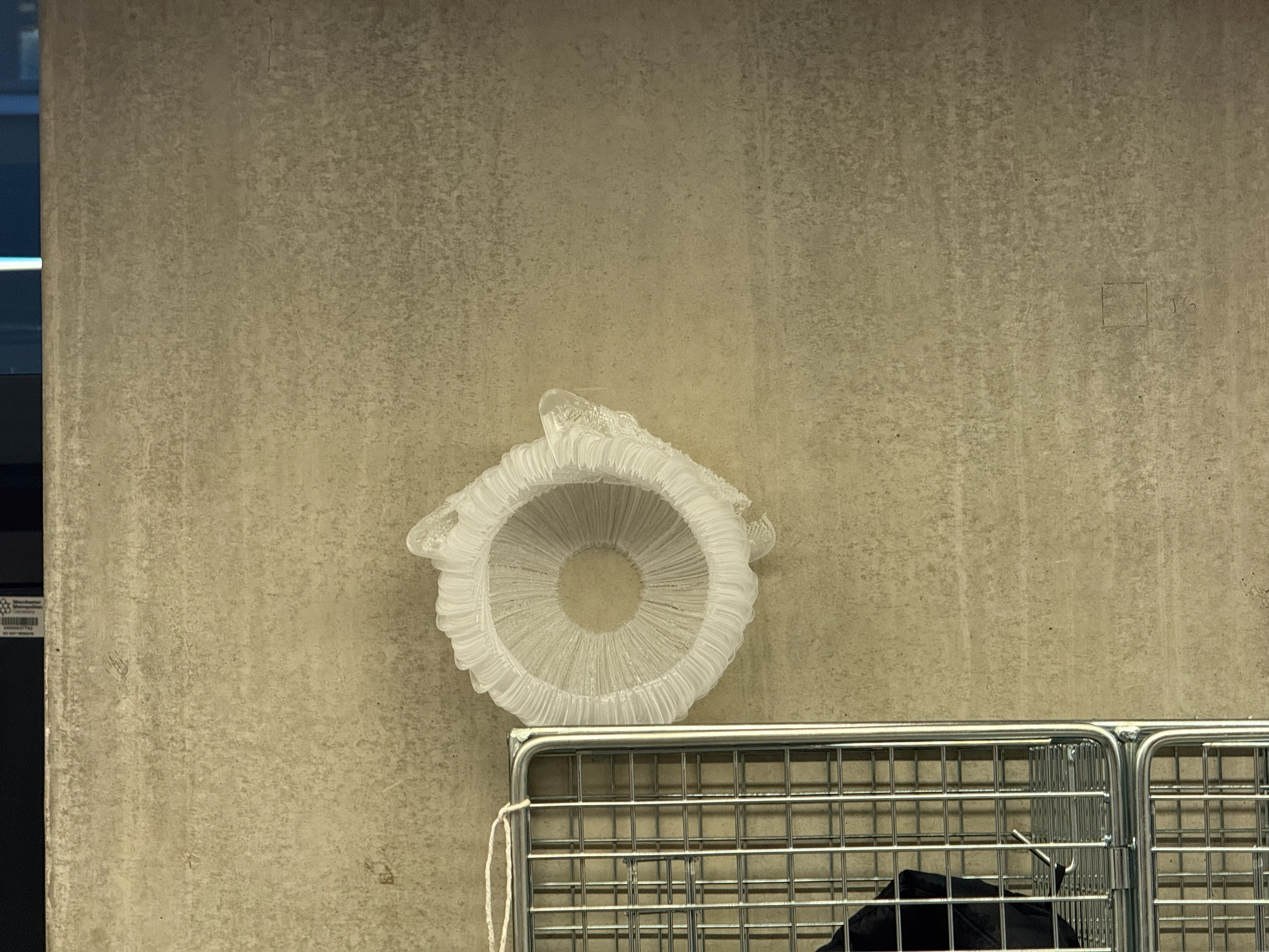
Pre mock up against concrete
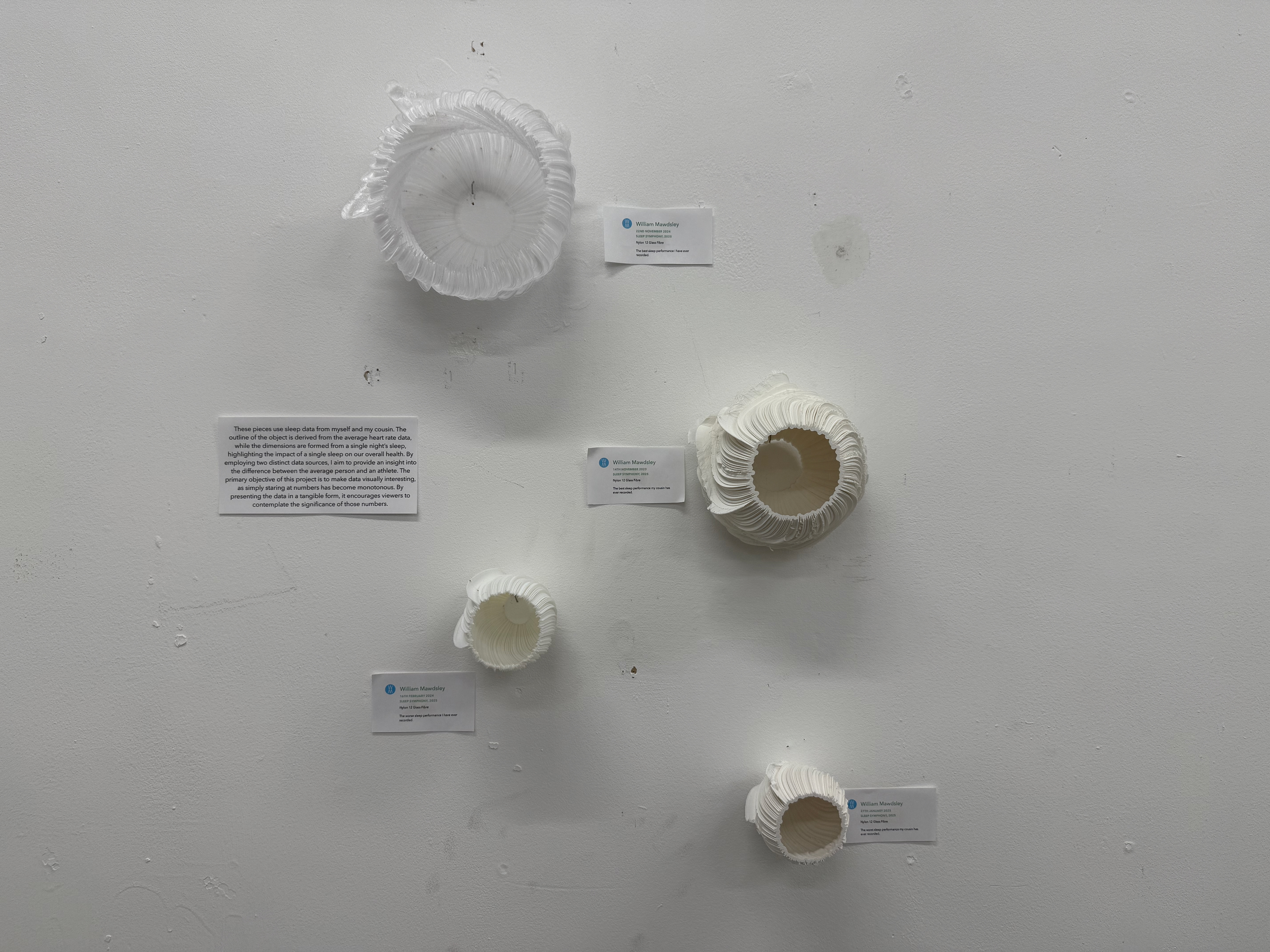
The curation
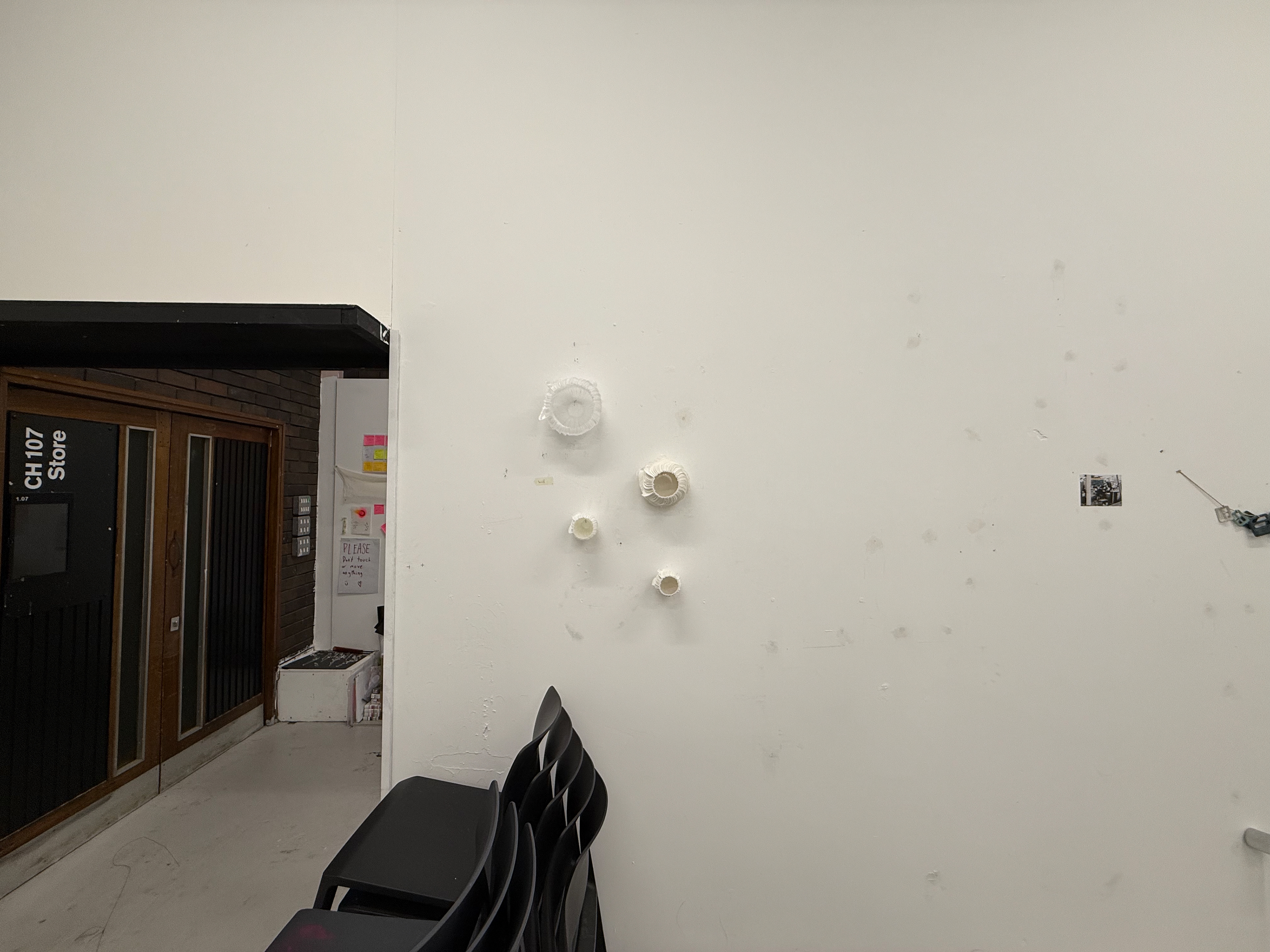
The curation from a far - they seem lost overall in the room
Feedback
Informative labels, but the top, clearest one, is lost in the wall.
Labels need some graphic design adjustments, and the content needs further refinement, but overall, they were good.
The clear, transparent one will not be the final piece; they will be grey, which should set itself apart from the white wall.
Viewer feedback
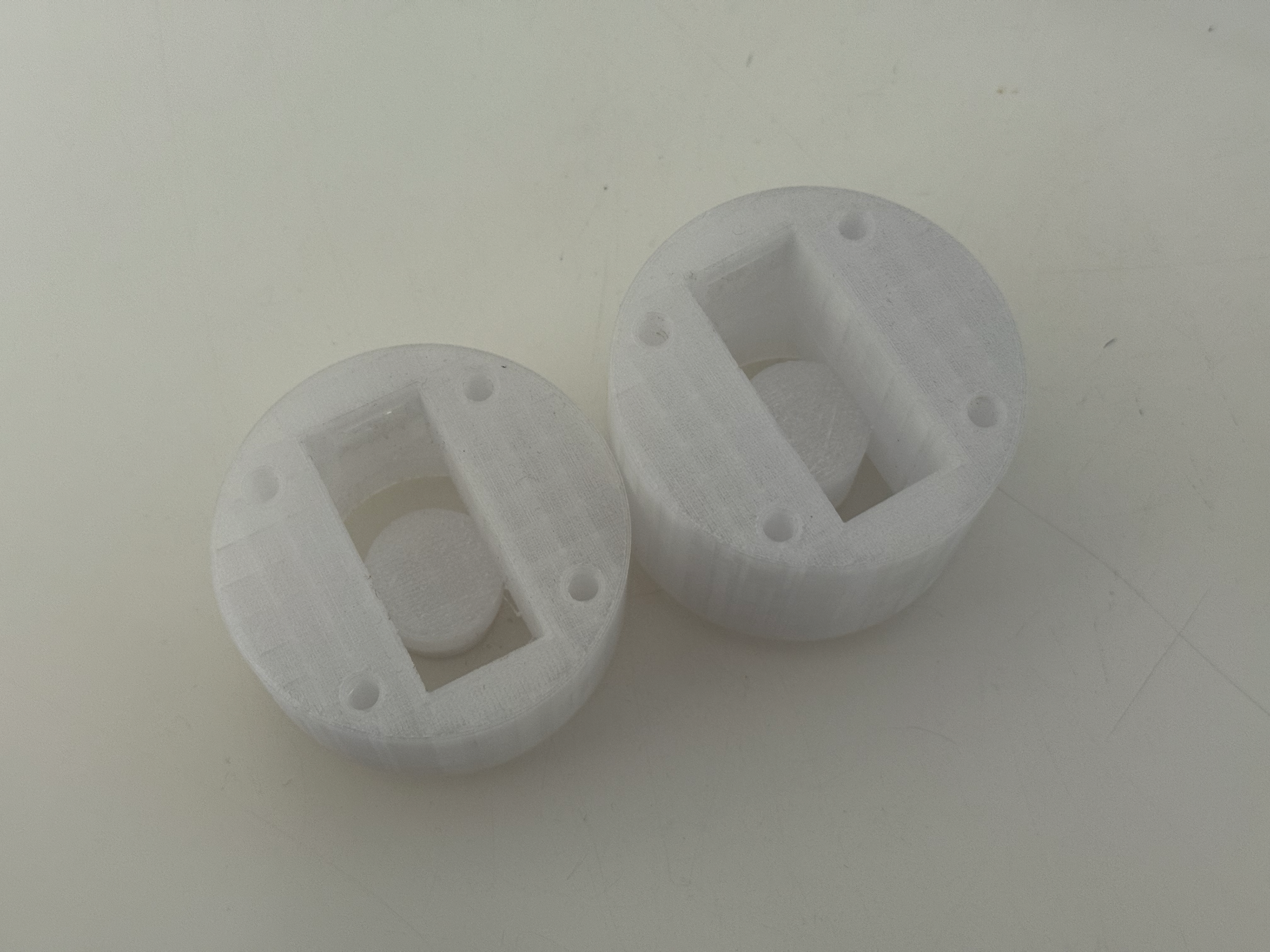
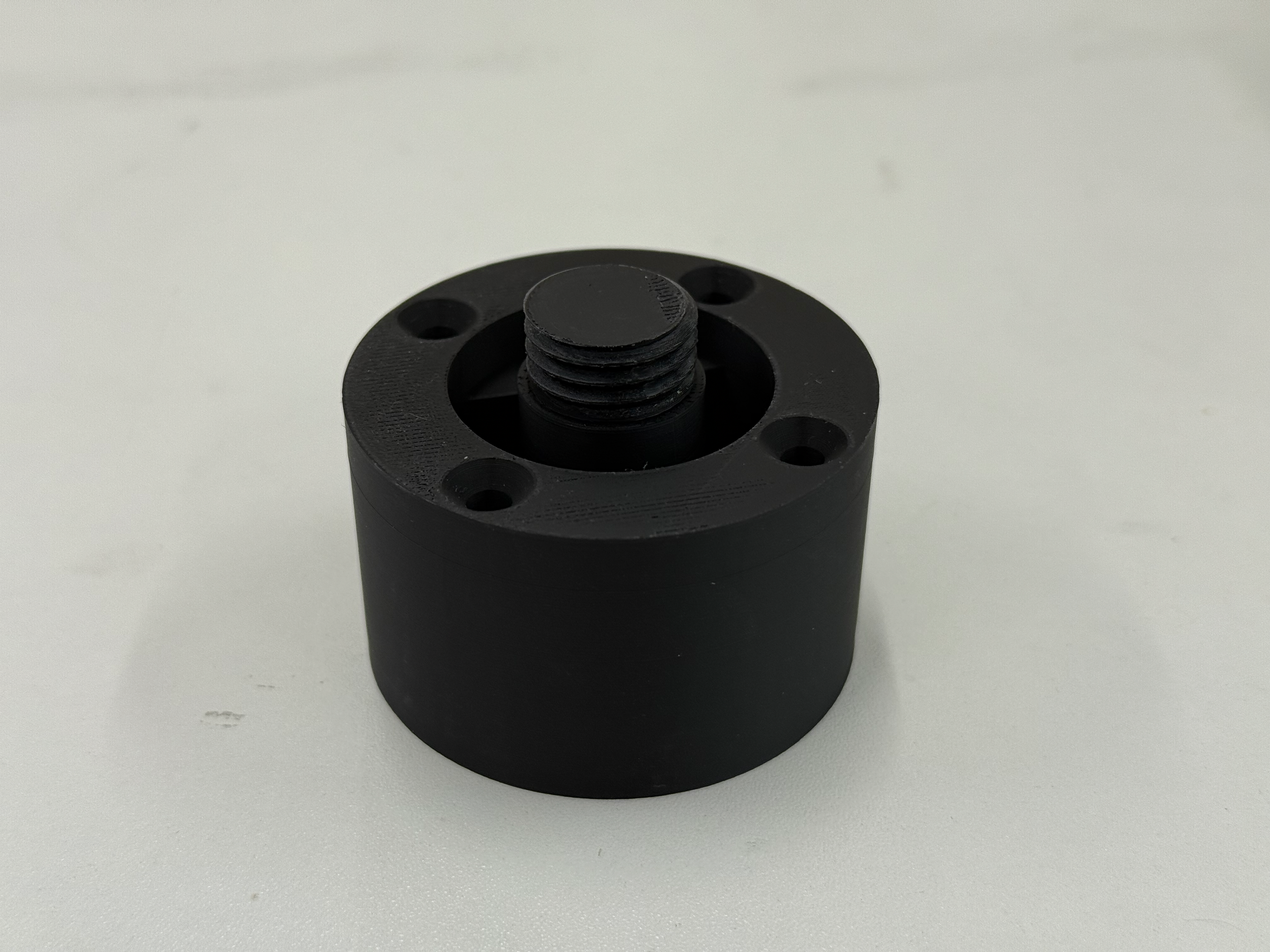
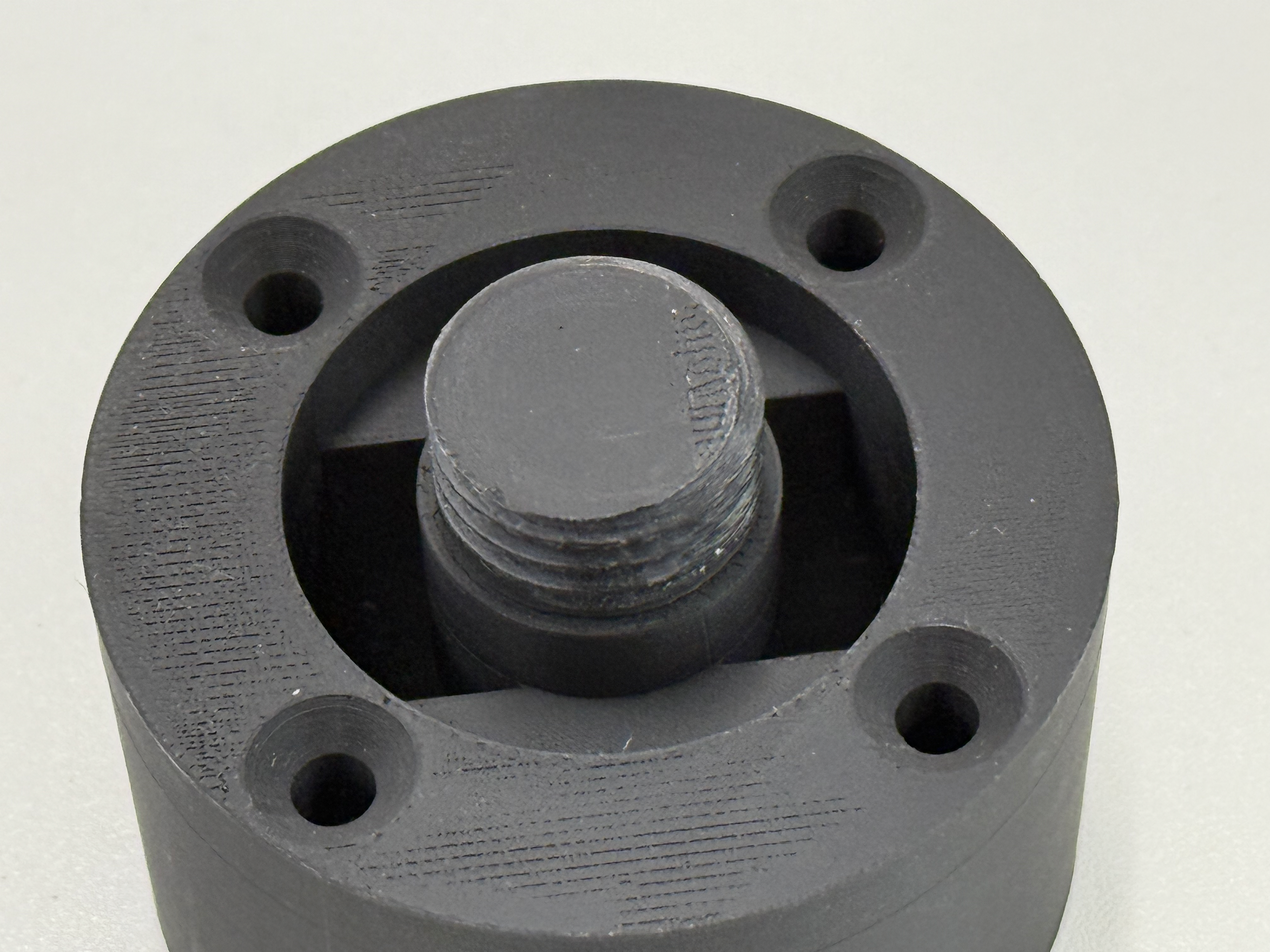
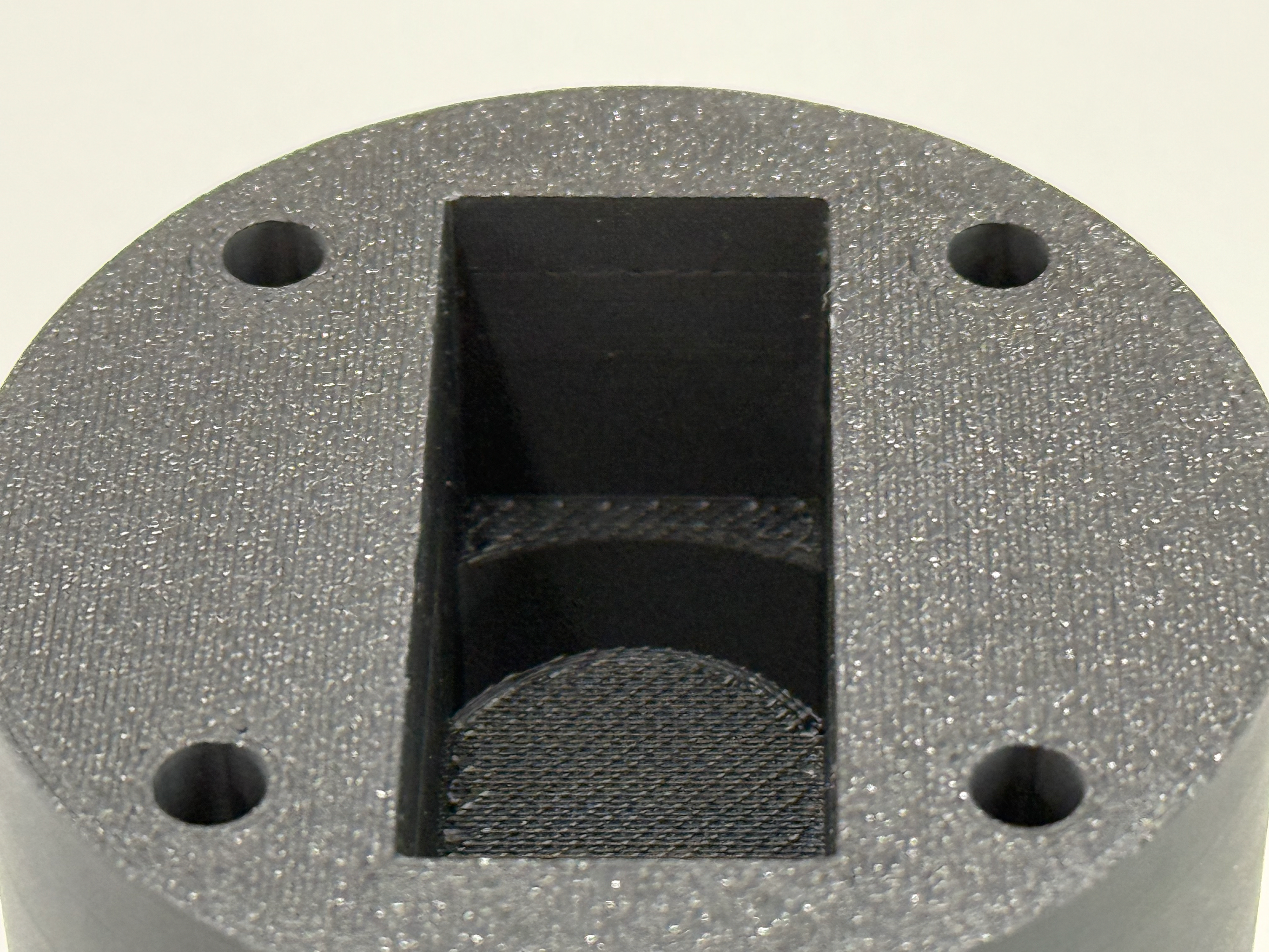
Concept 2 mounting system
Deciding on taking the screw method forward, I printed a version that would fit one of the scaled-down nylon versions. This worked and fitted very well, which meant I didn't have to adjust the locking aspect. Now I have to integrate LEDs into this mounting system and make it look as good as the object itself.
Holding using the mount. Hopefully, the LEDs will direct the light out the sides rather than the front; otherwise, I can just use something to block the light from the front and reflect it back into the object and out the sides.
Refinement Direction
Following my formative review 2, I have a choice to make of either refining the object itself or focusing on bringing in the lighting aspect.
I am really happy with the object as it is and I don't want to change it except for refining the fins that have not printed perfectly. So I am keen to continue with the lighting system, especially following the success of this mounting solution.
Bringing light into this project will help give the piece a meaning; currently, it is a visual representation of data, lots of those exist. I want to create something that's interesting and interactive, and by creating a nightlight, it doesn't remove the focus from data visualisation but reinforces it and makes it an interesting piece. A fictional piece of art.
Lighting
Would it work?
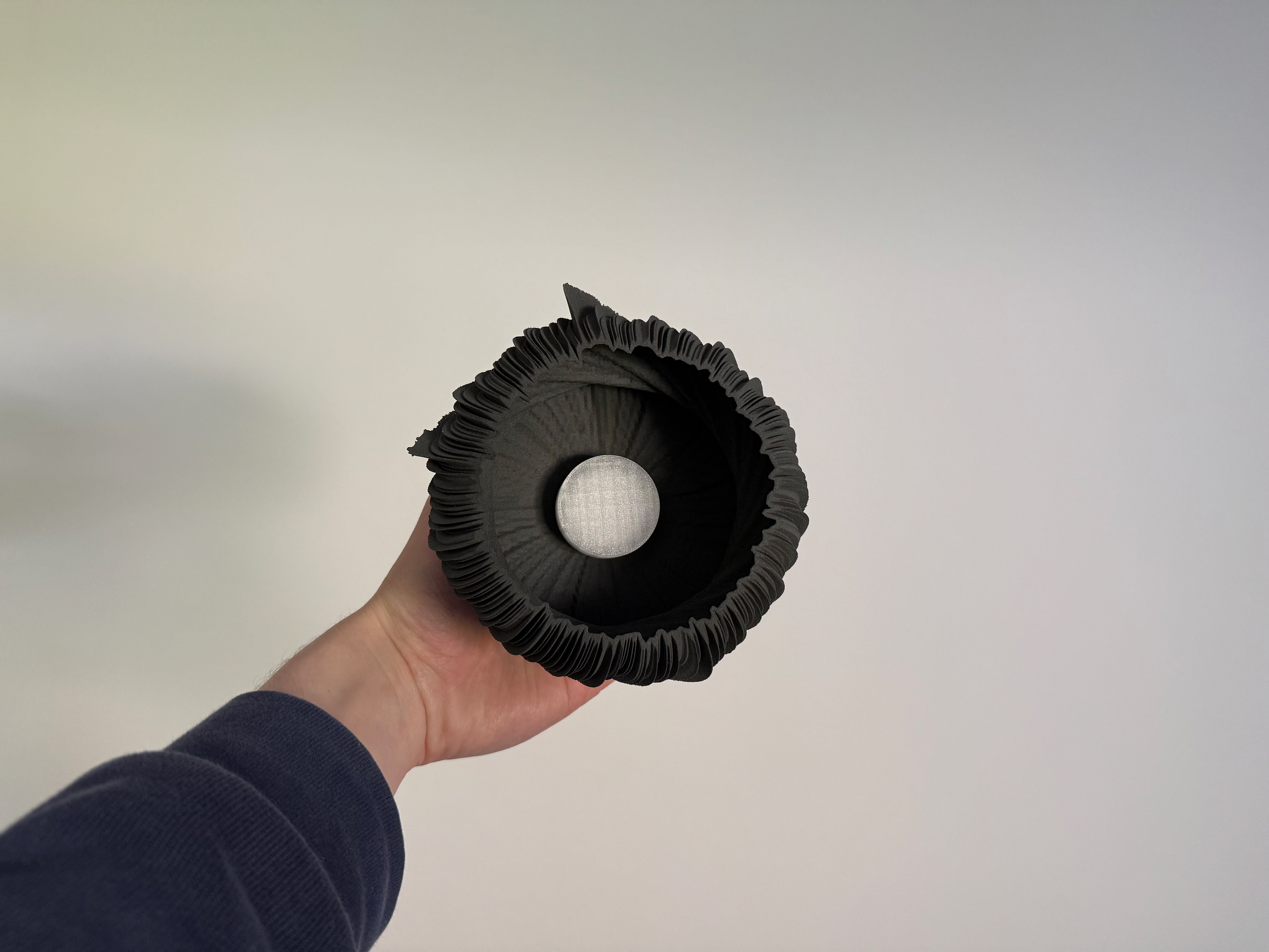
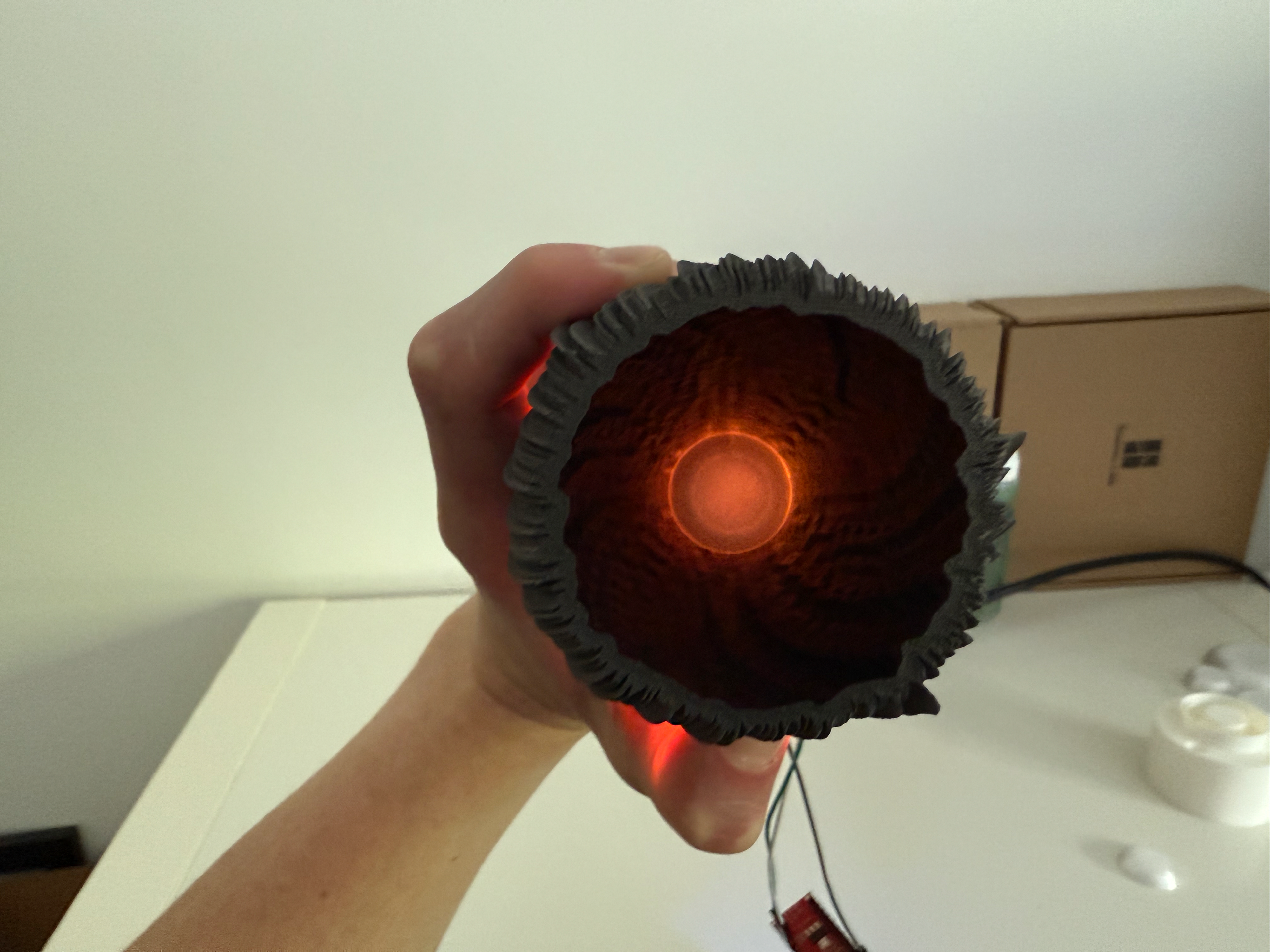
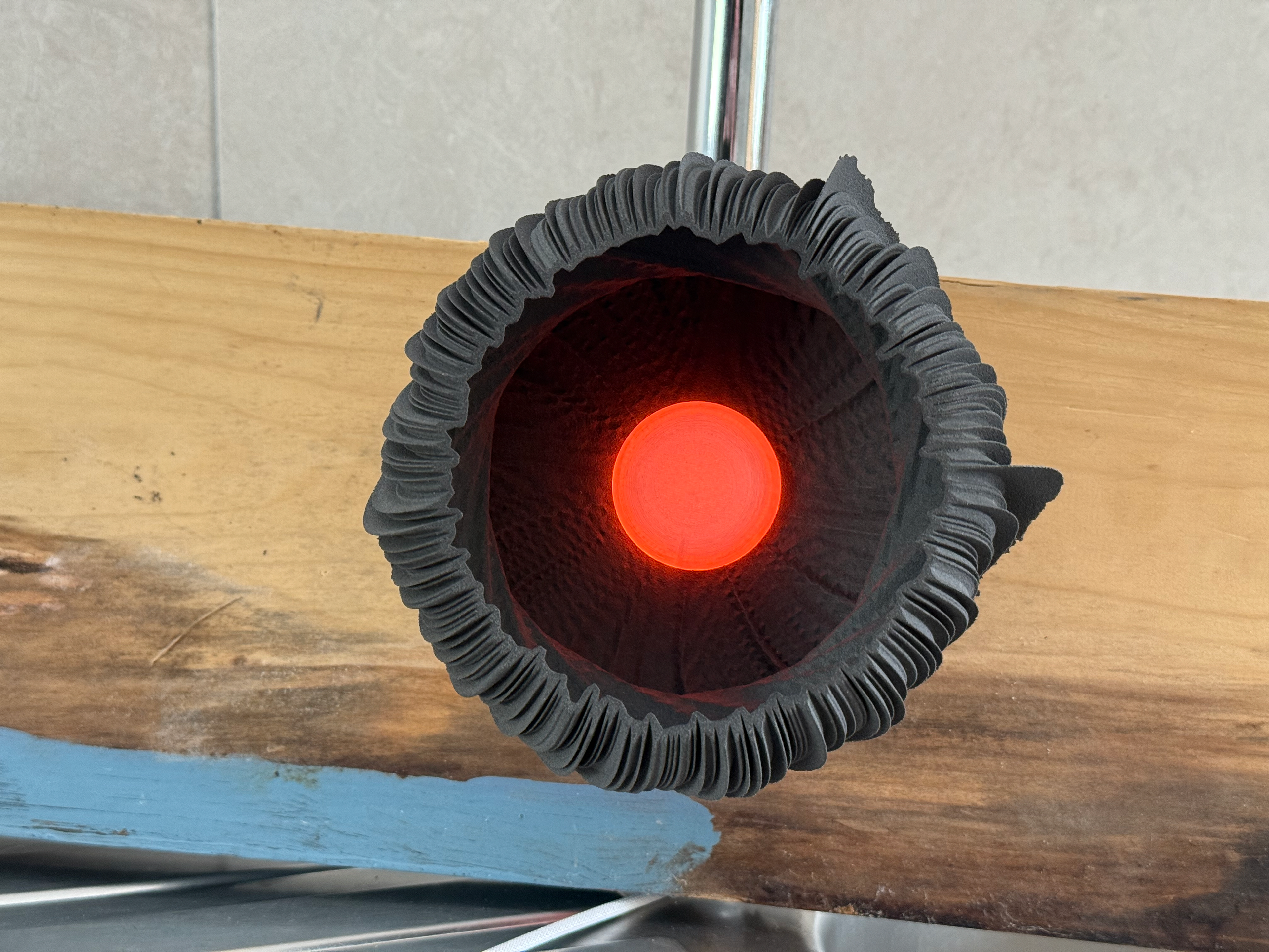
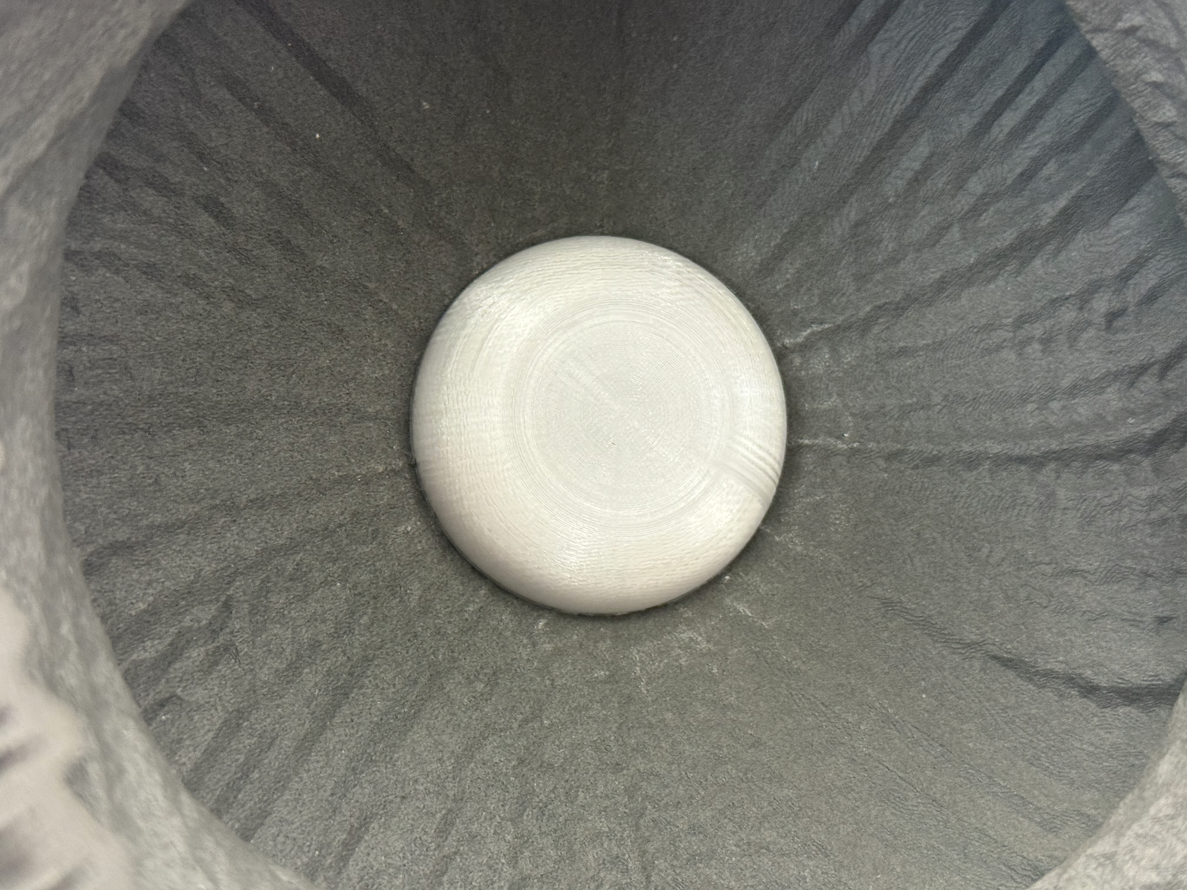
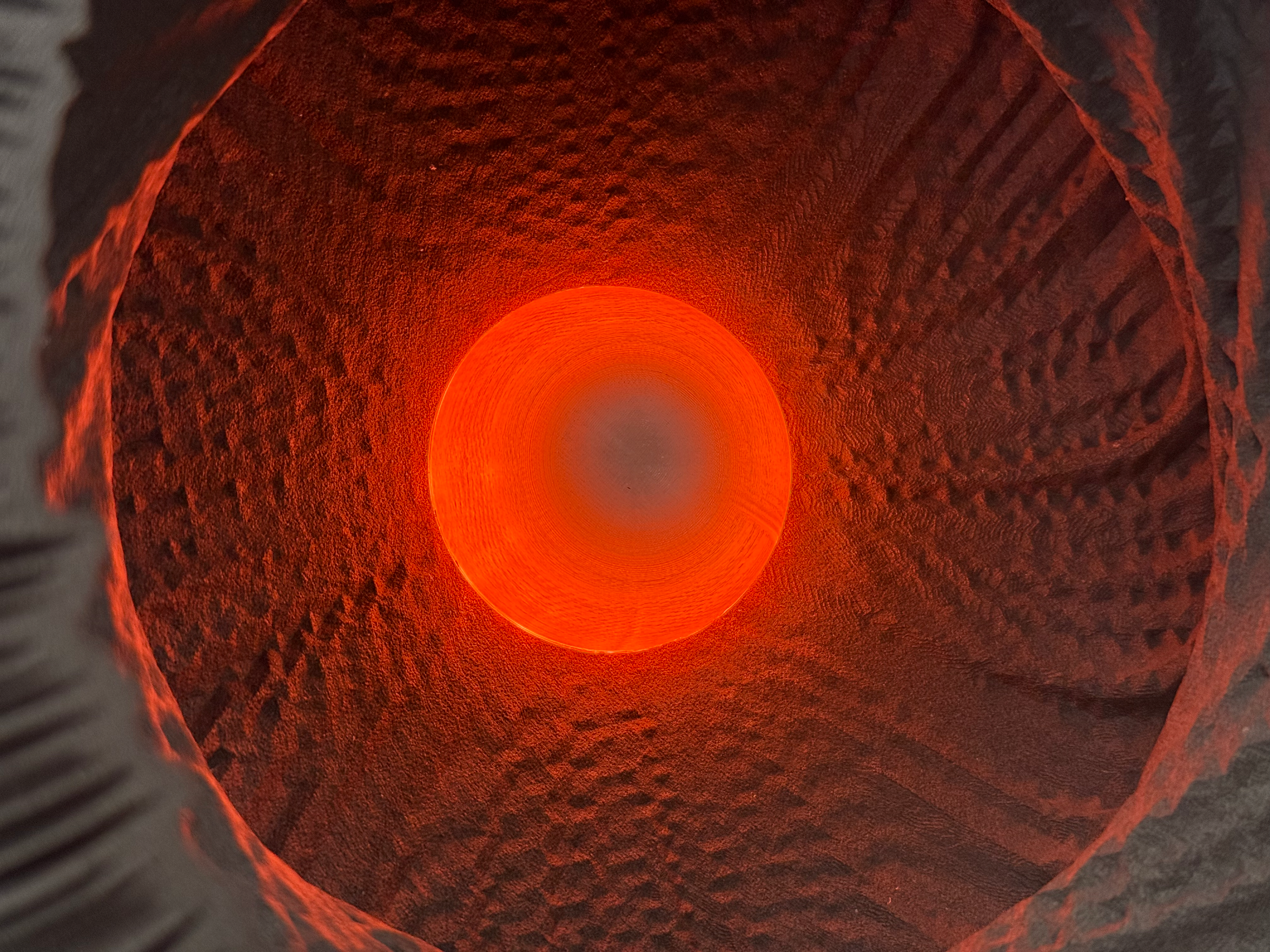
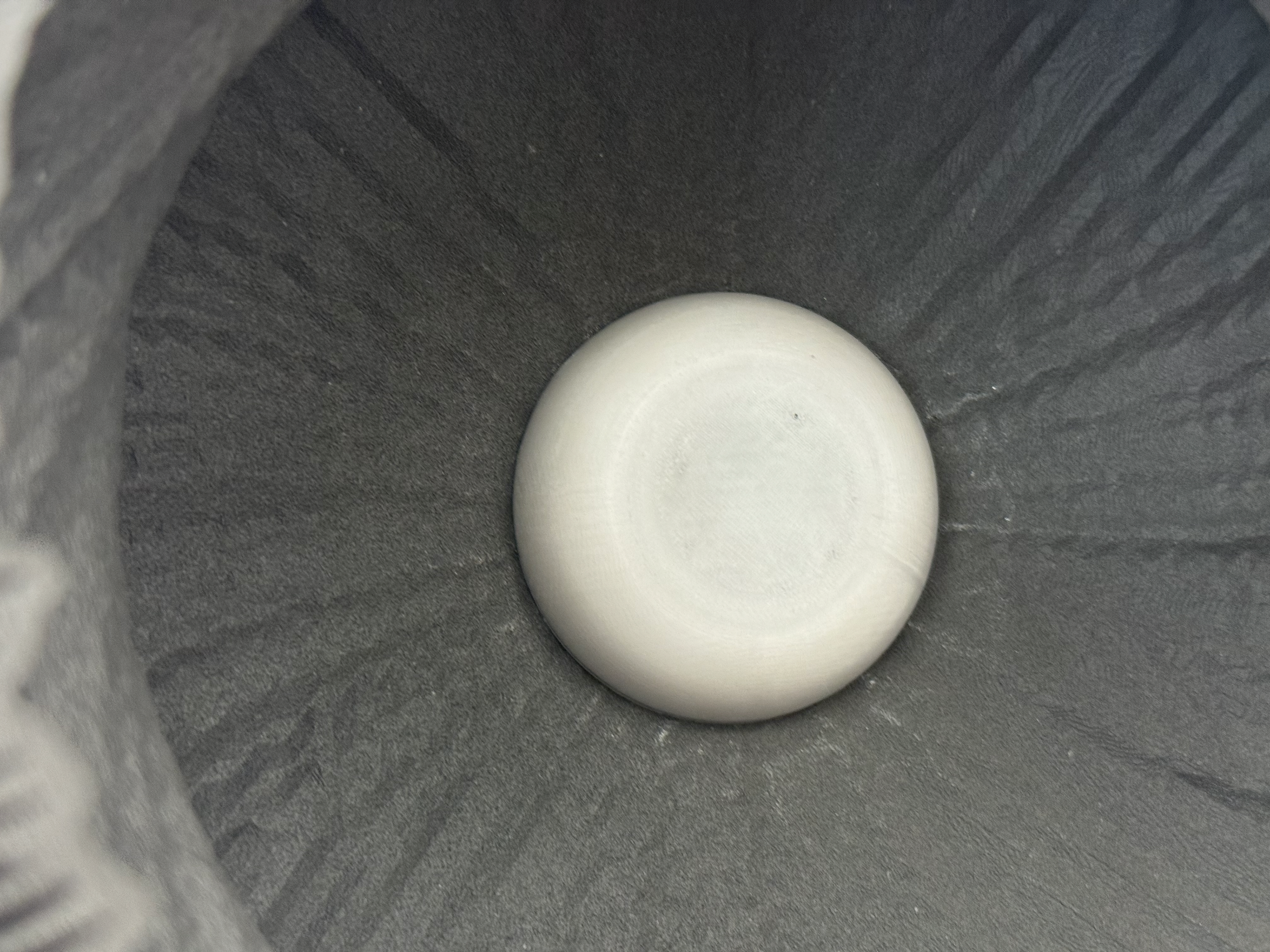
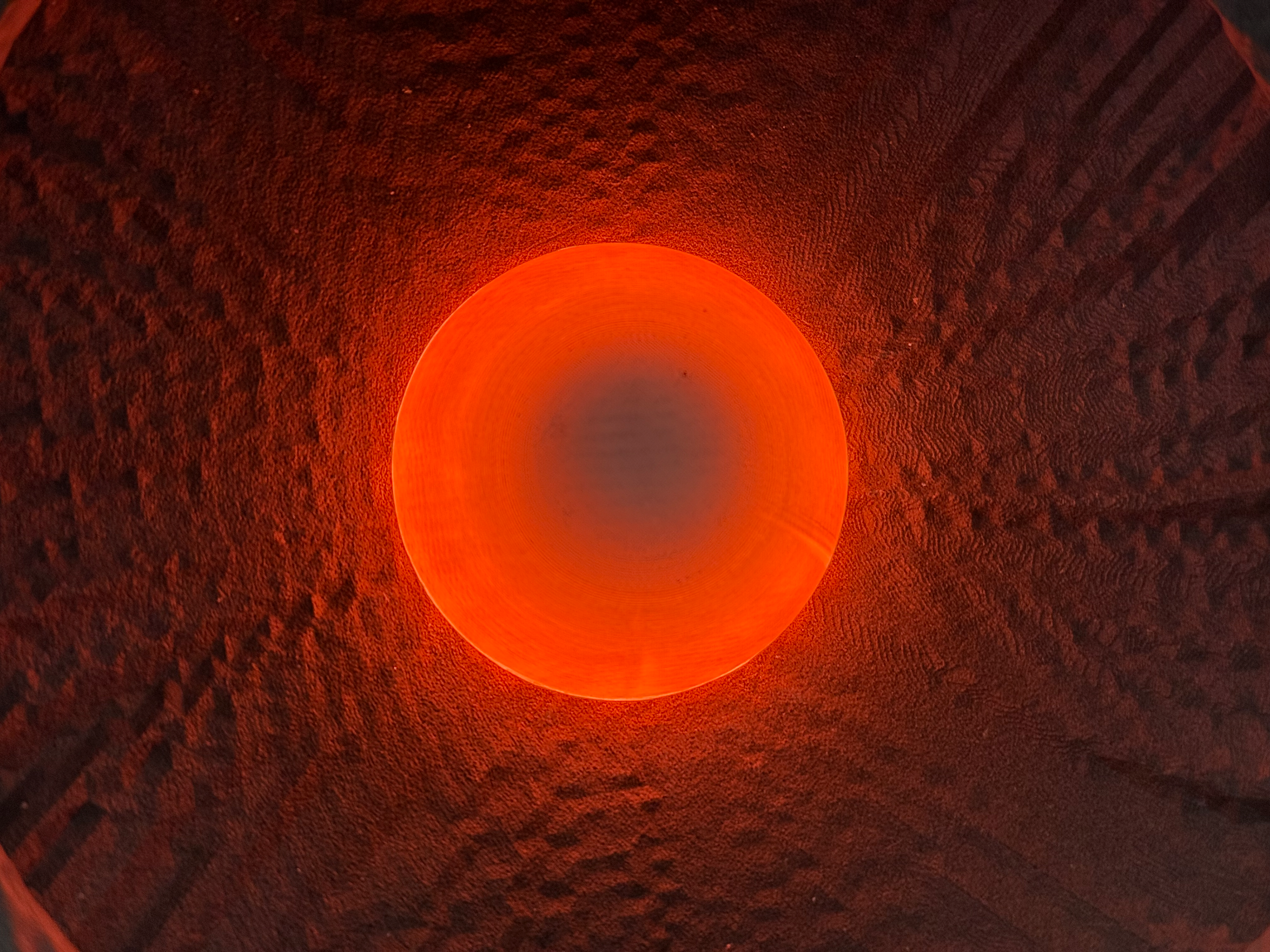
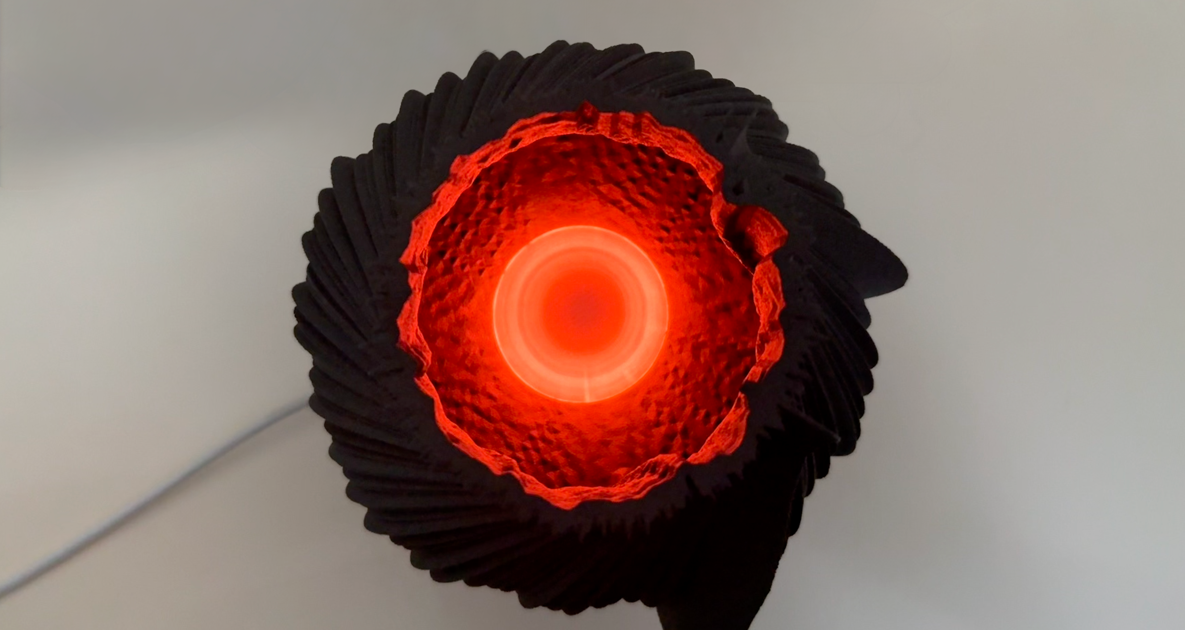
After collecting the scaled-down nylon pieces from Print City, I wanted to make sure that I could use lighting and it would enhance the inside of my object, so I found a tea light and placed it inside my object.
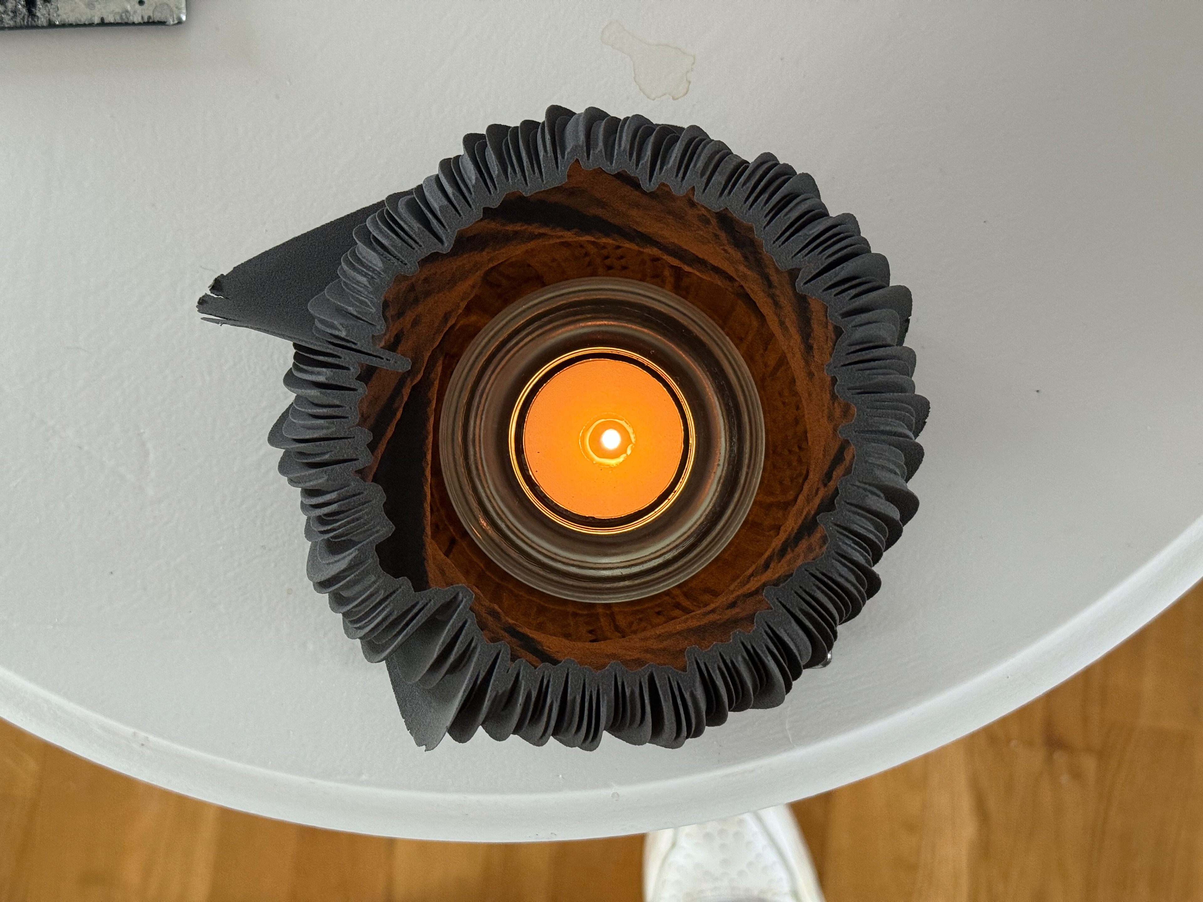
Direct on looks quite hypnotic
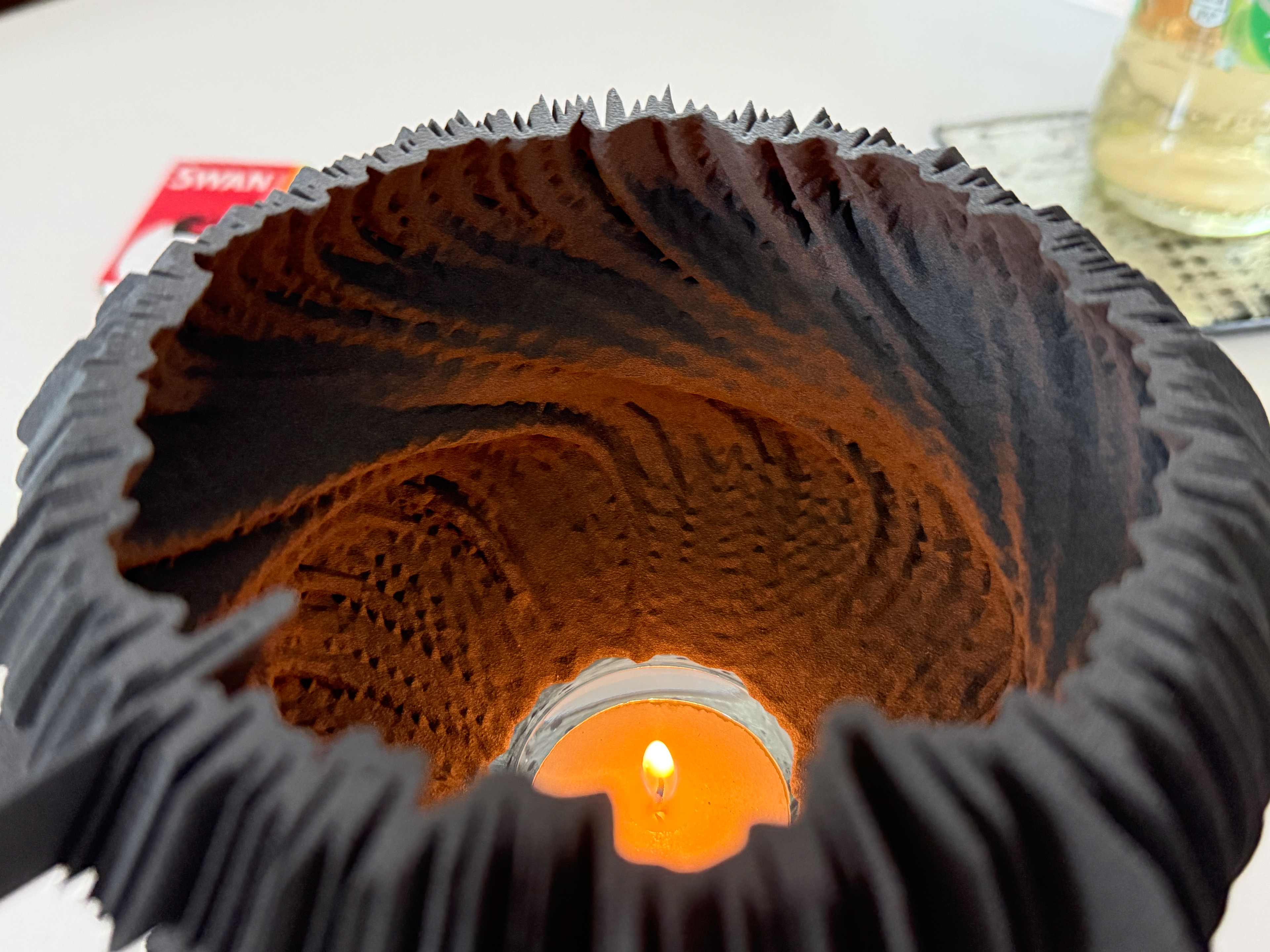
Lights up the edges really well
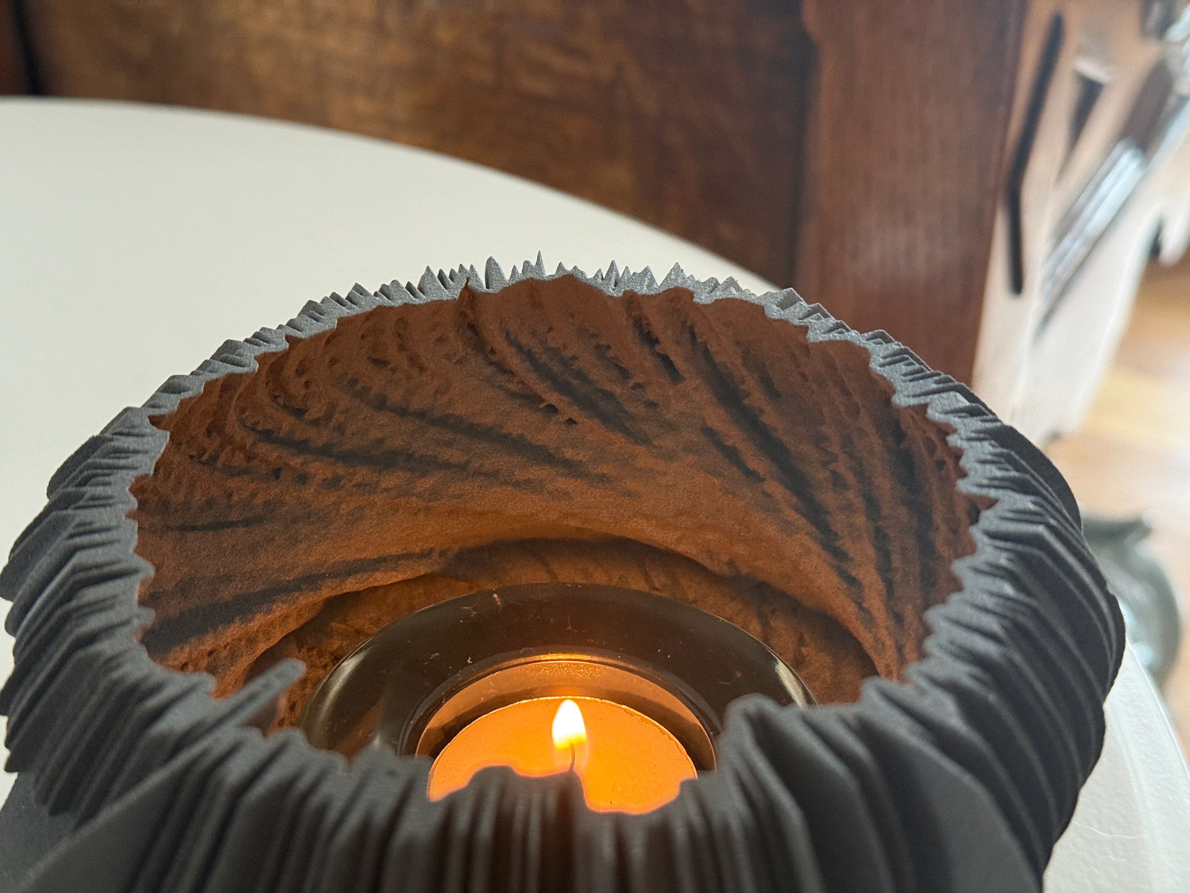
Fades away at is gets toward the brim
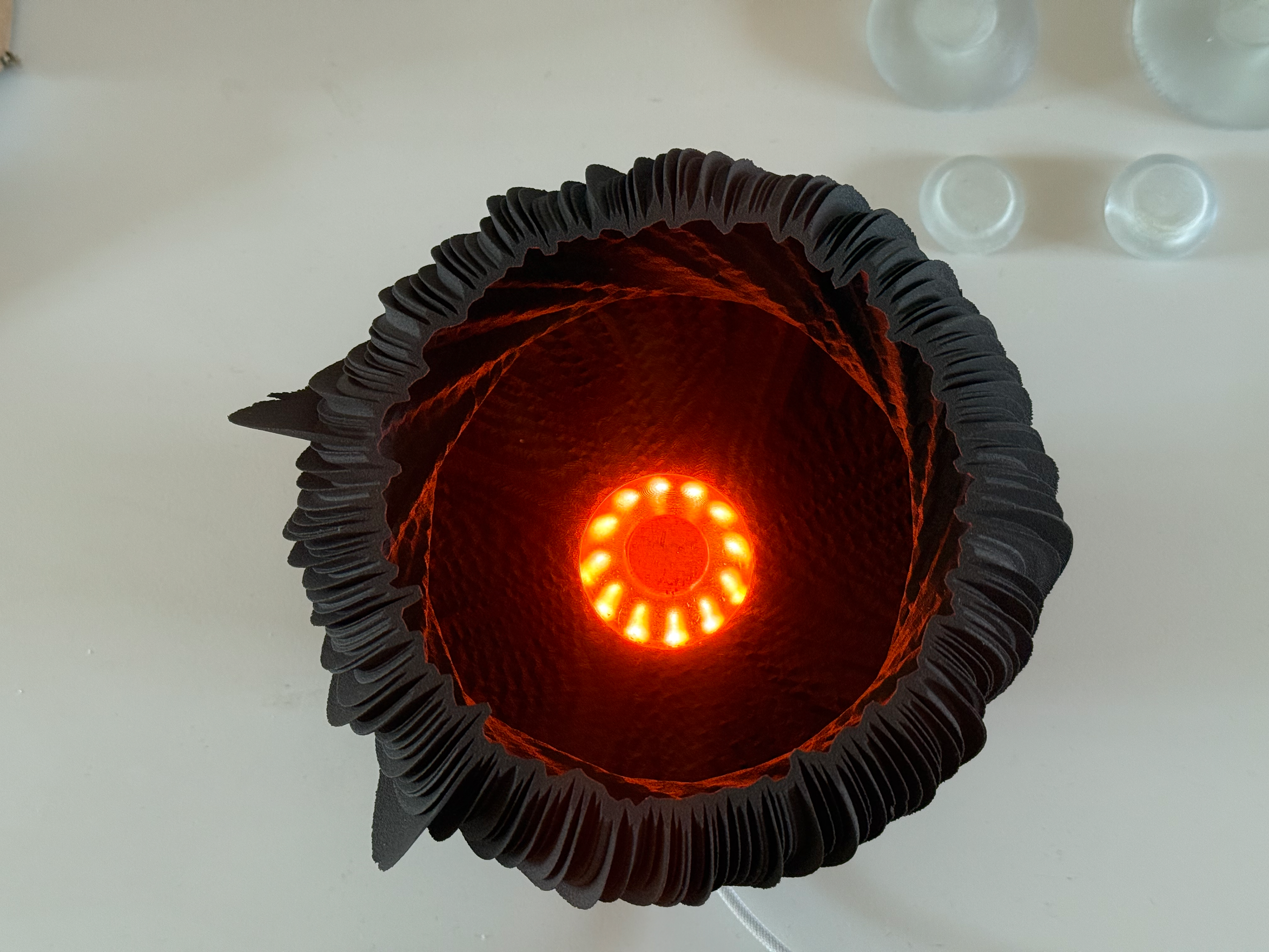
I really liked this orange glow, and this was the moment I decided absolutely to go for lighting. It brings out the curves of the inside and highlights the sections where the software has made small cuts, like tiny traces of data. Imperfections made by software, similar to the imperfections of my Whoop data.
Mounting integration
Now I had a nylon piece and a mounting system, I wanted to understand if I could actually use PETG or maybe I'd have to find a different material to work with. I placed an iPhone underneath with its flashlight and watched it glow.
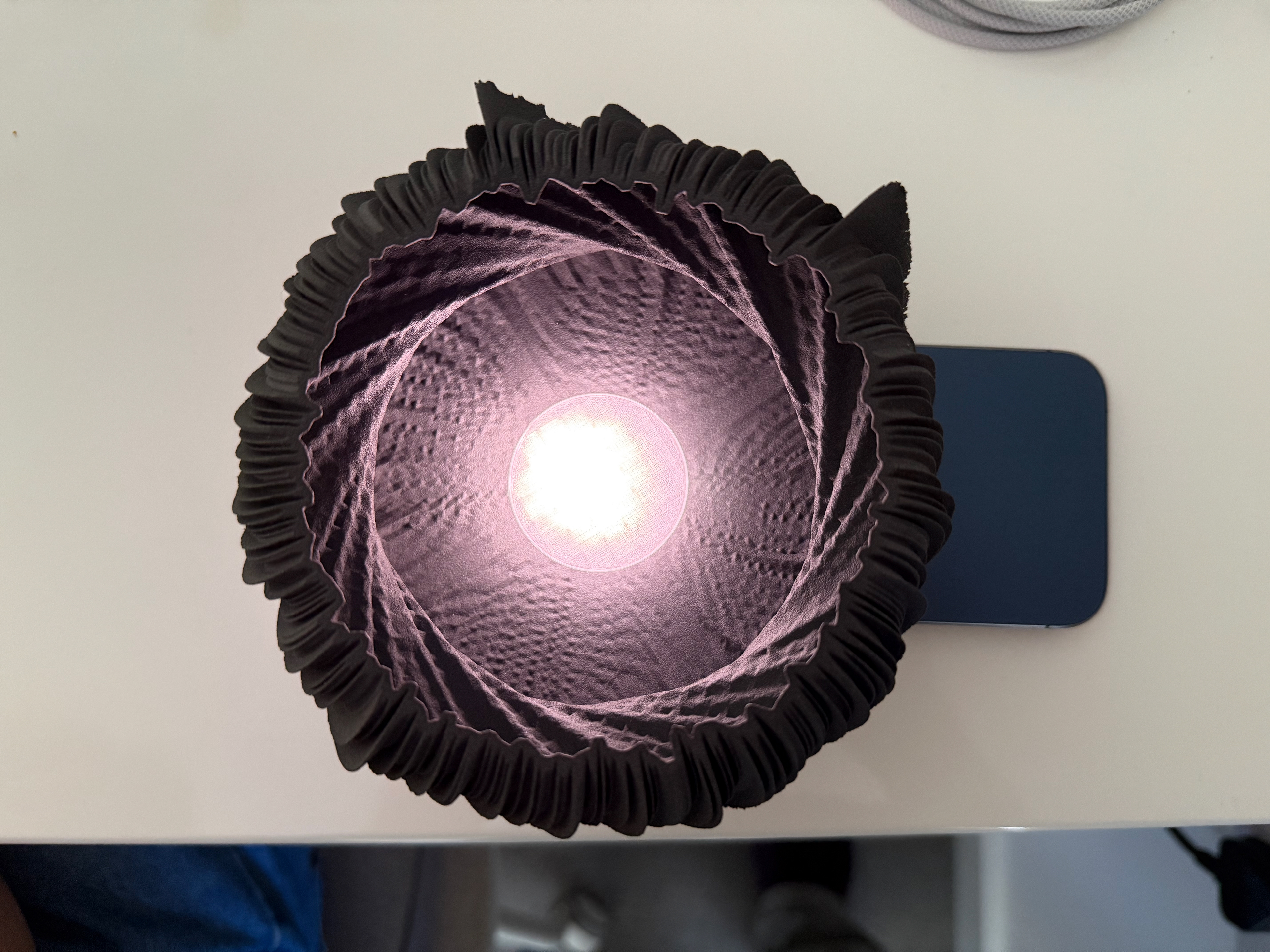
Direct on is quite harsh
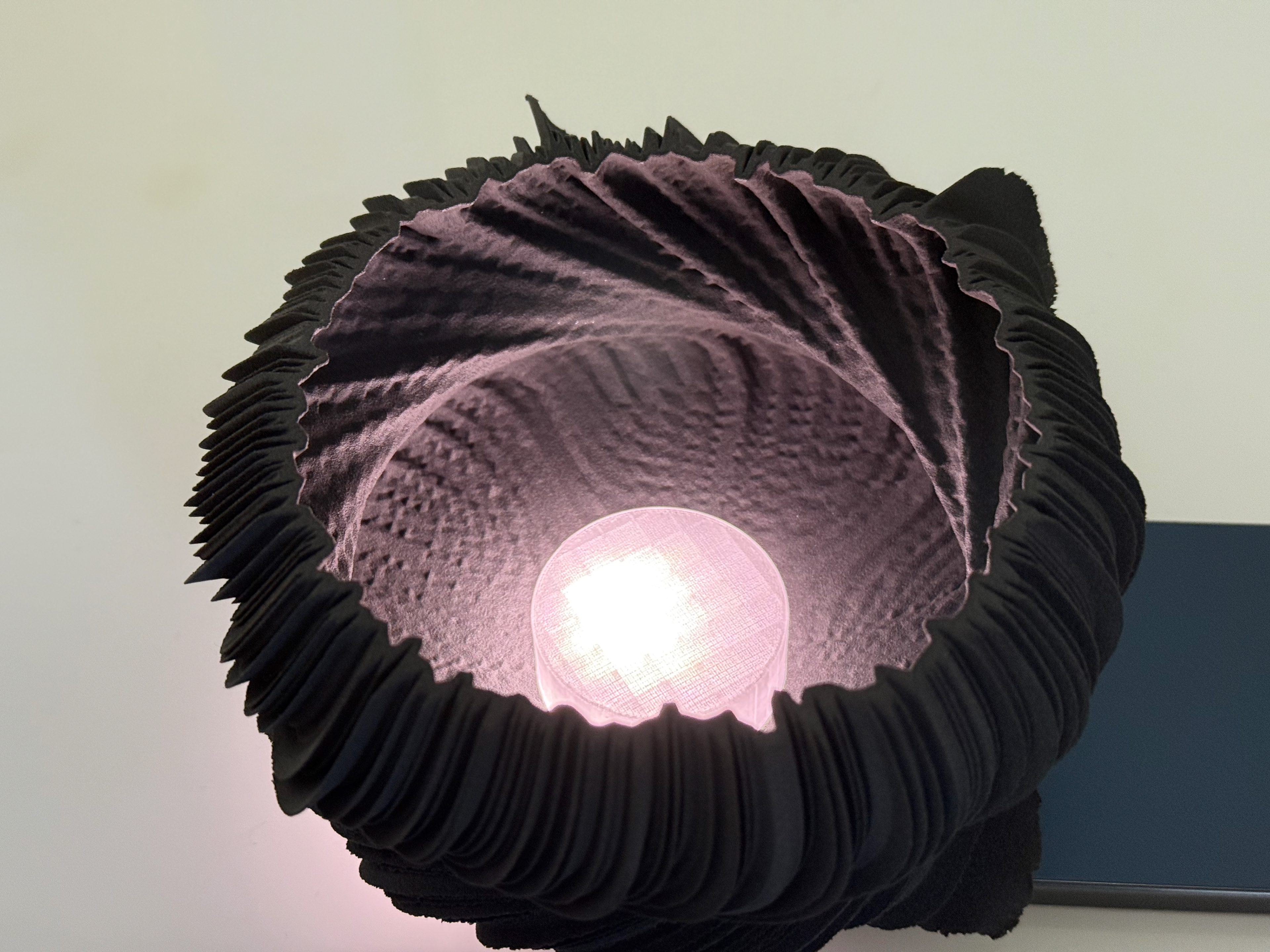
Lights up the edges well
Individual LED's
Once I knew PETG would work, I went to test what I actually could use to provide a light source. Geoff showed me a kit that includes everything I need to test this. After using a YouTube tutorial, I had the LEDs lighting up. However, neither single nor multiple LEDs could make them bright enough for the inside of the object to be lit up when the overhead light is on. This is an important consideration because this needs to work in all lights, especially if I decide to light the externals of my object too.
Overhead lights on
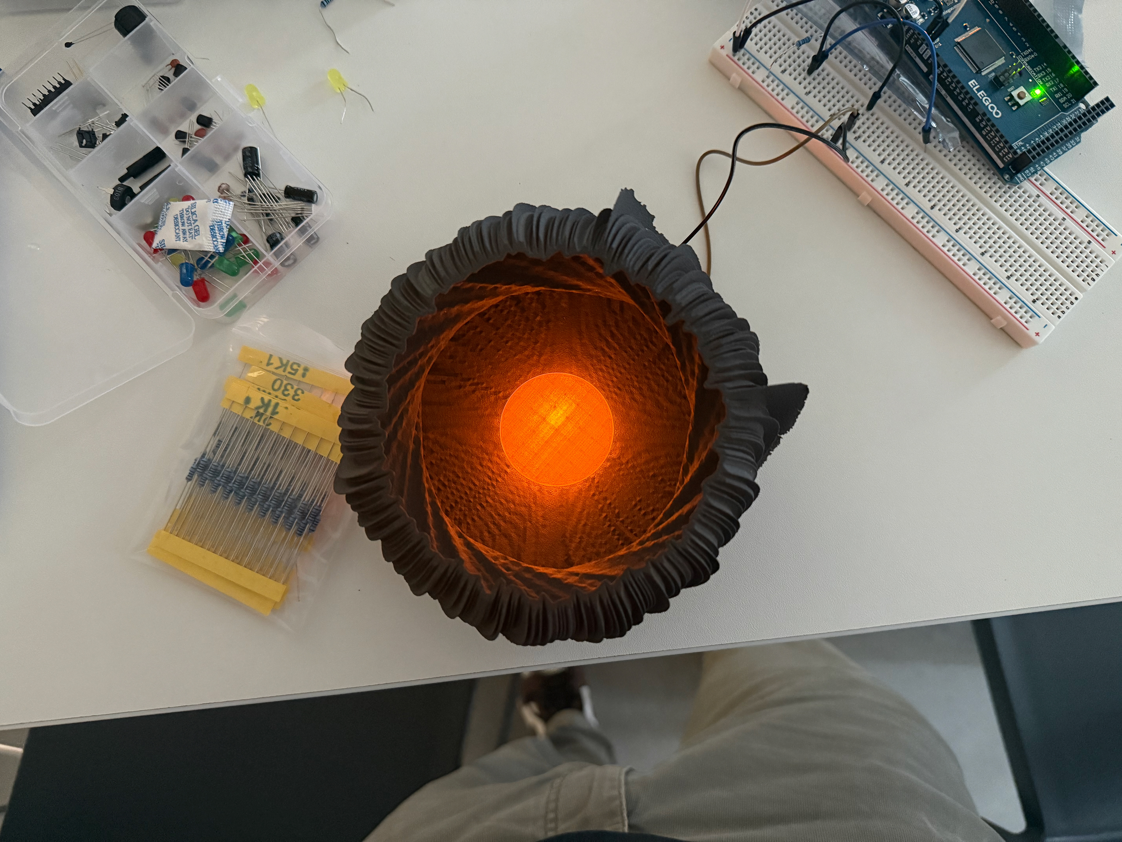
Overhead lights off
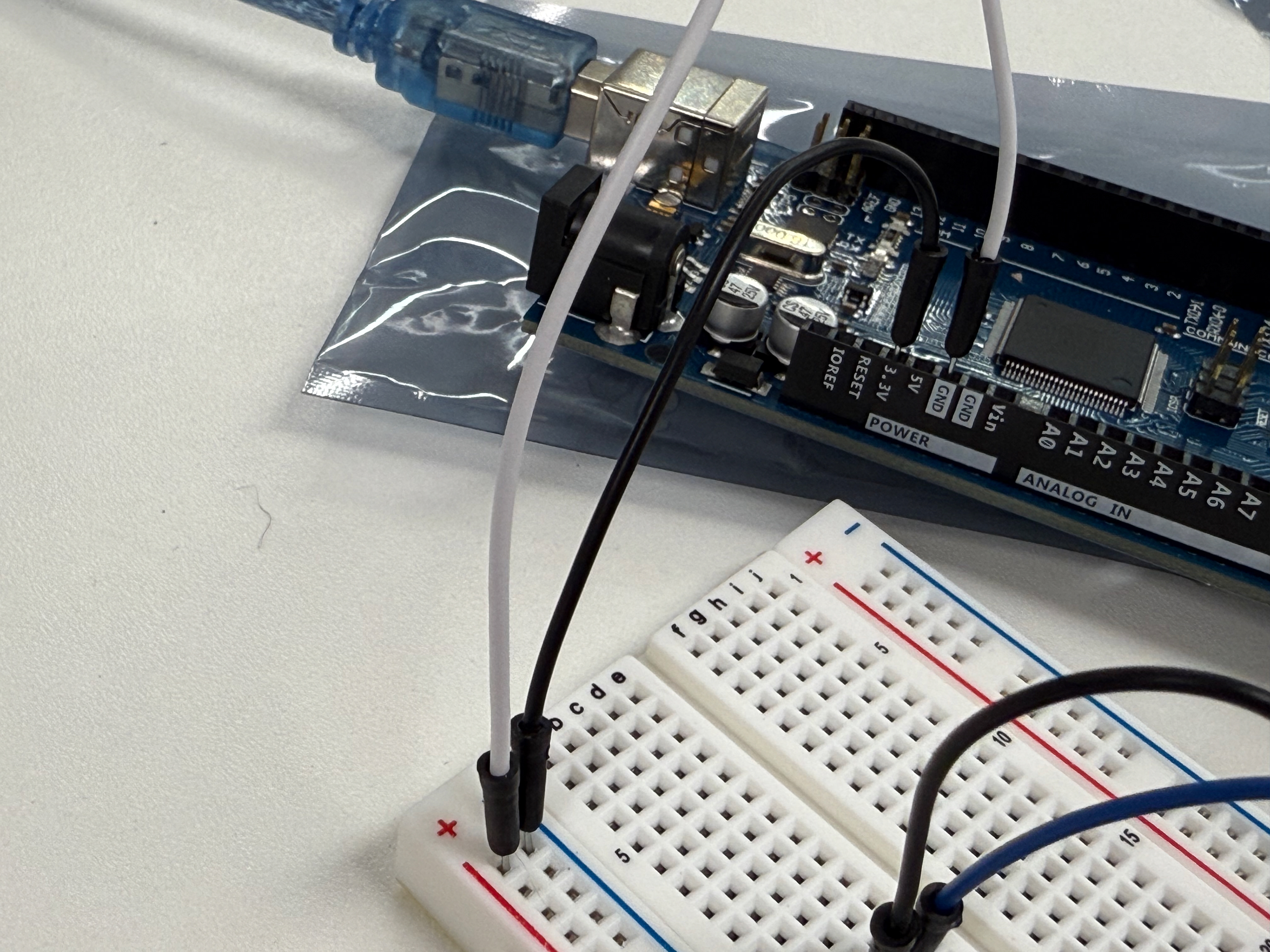
Connections into the Elegoo
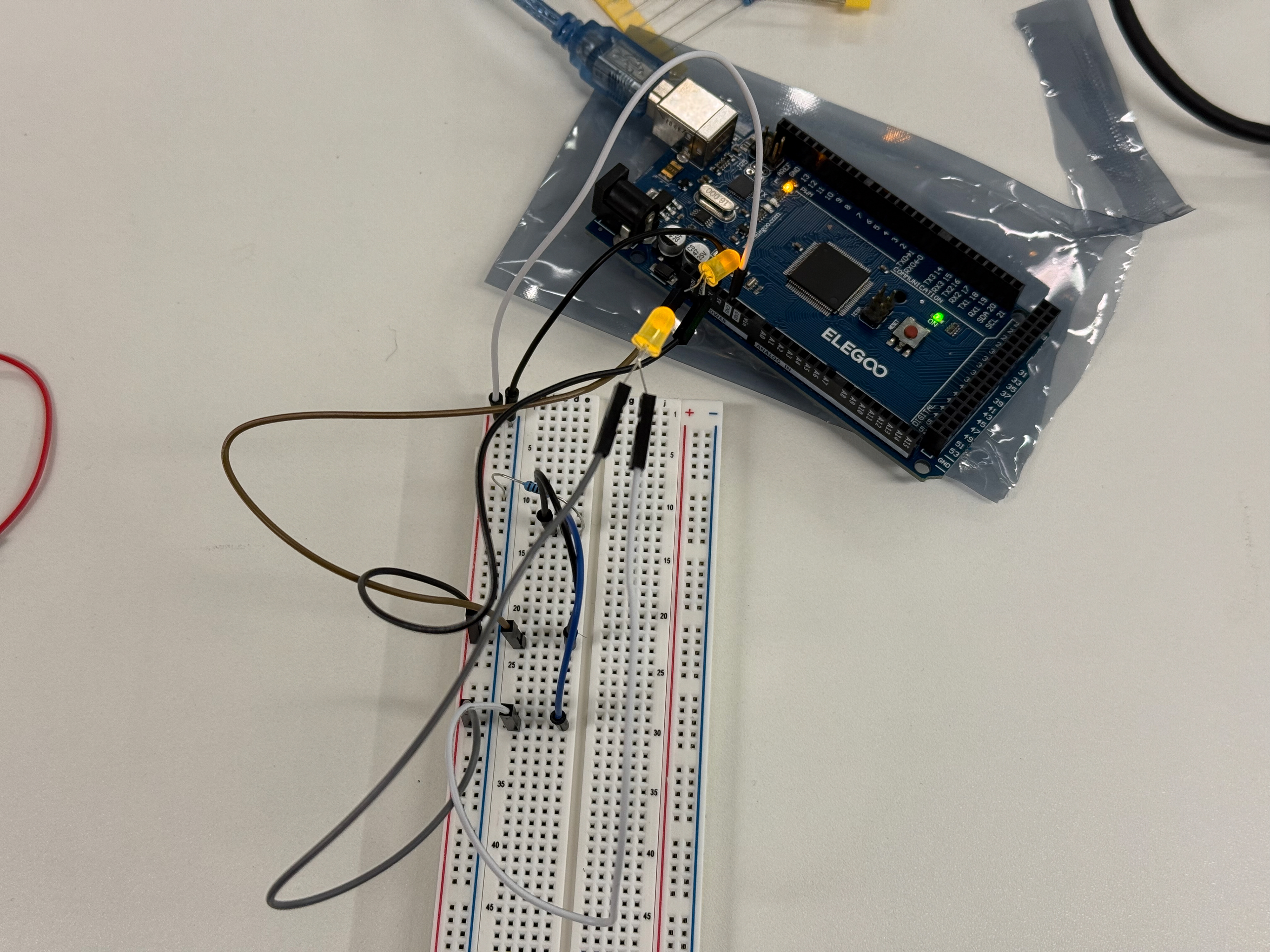
Elegoo into the breadboard connections
NeoPIxel
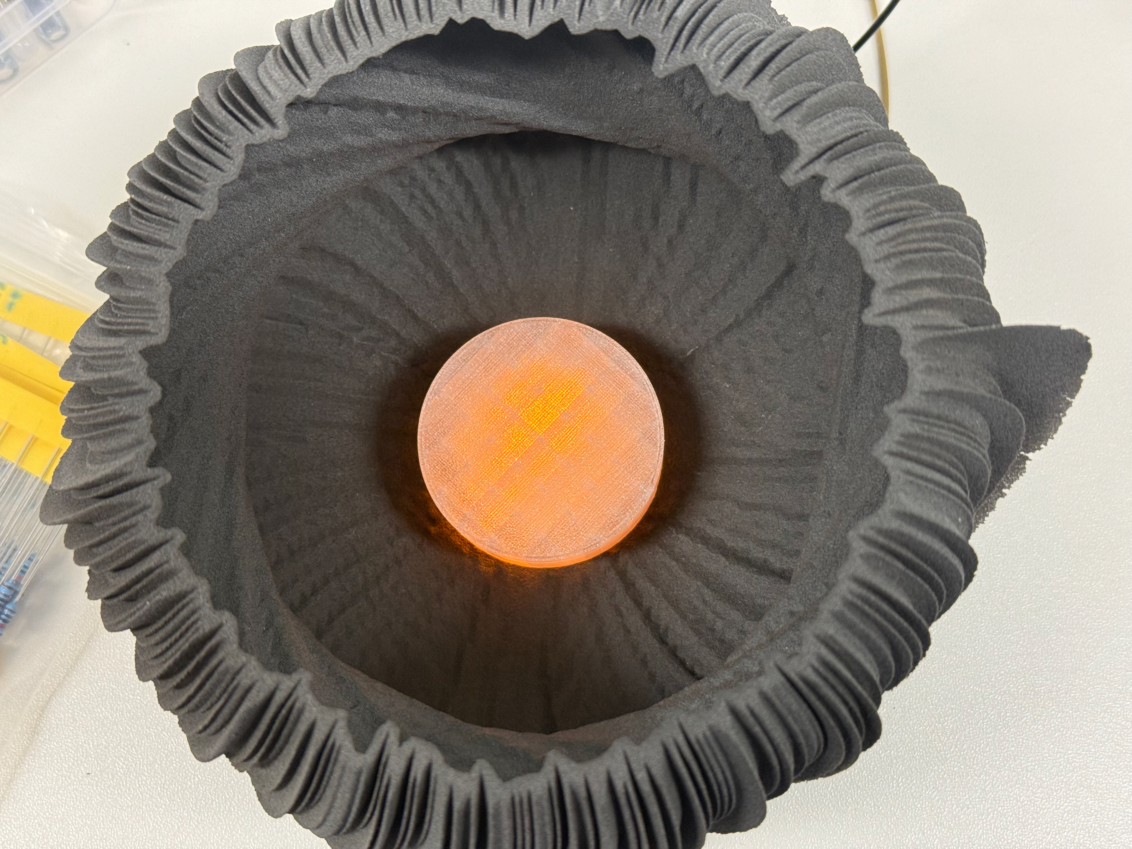
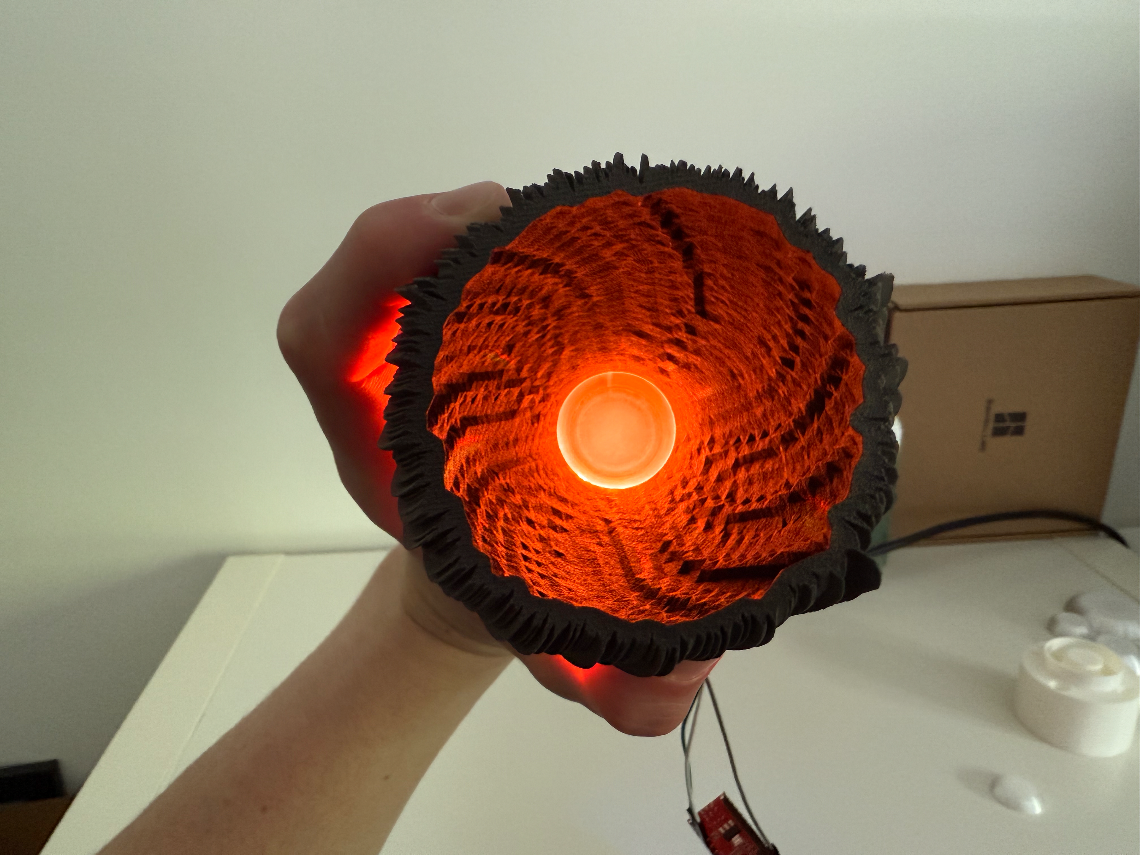
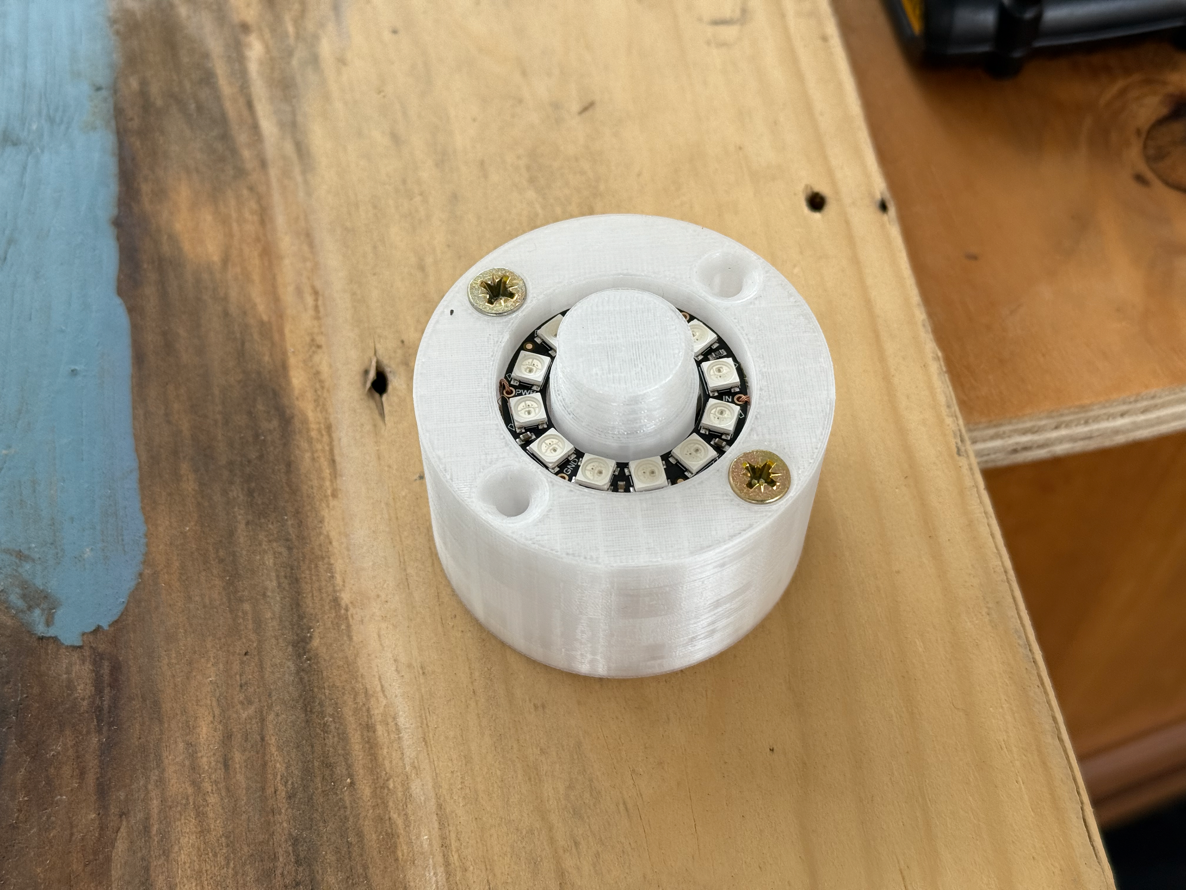
Following my tutorial with Geoff (31/03/2025), I looked into a NeoPixel LED Ring and purchased one. I tweaked the top part of the mount to accommodate it and printed it. Once the NeoPixel Ring arrived, it was obvious how to connect it to the Elegoo. I then asked Grok for some code that would light it up orange, which it provided, and then I complied and uploaded the code to the Elegoo, which then made the ring light up. This worked well as it provided the brightness needed in both dark and light environments; the only issue is that the individual LEDs are clearly visible, so now I need to work on hiding them without reducing brightness as well as controlling four of them simultaneously, without compromising on aesthetics.
The refined mount
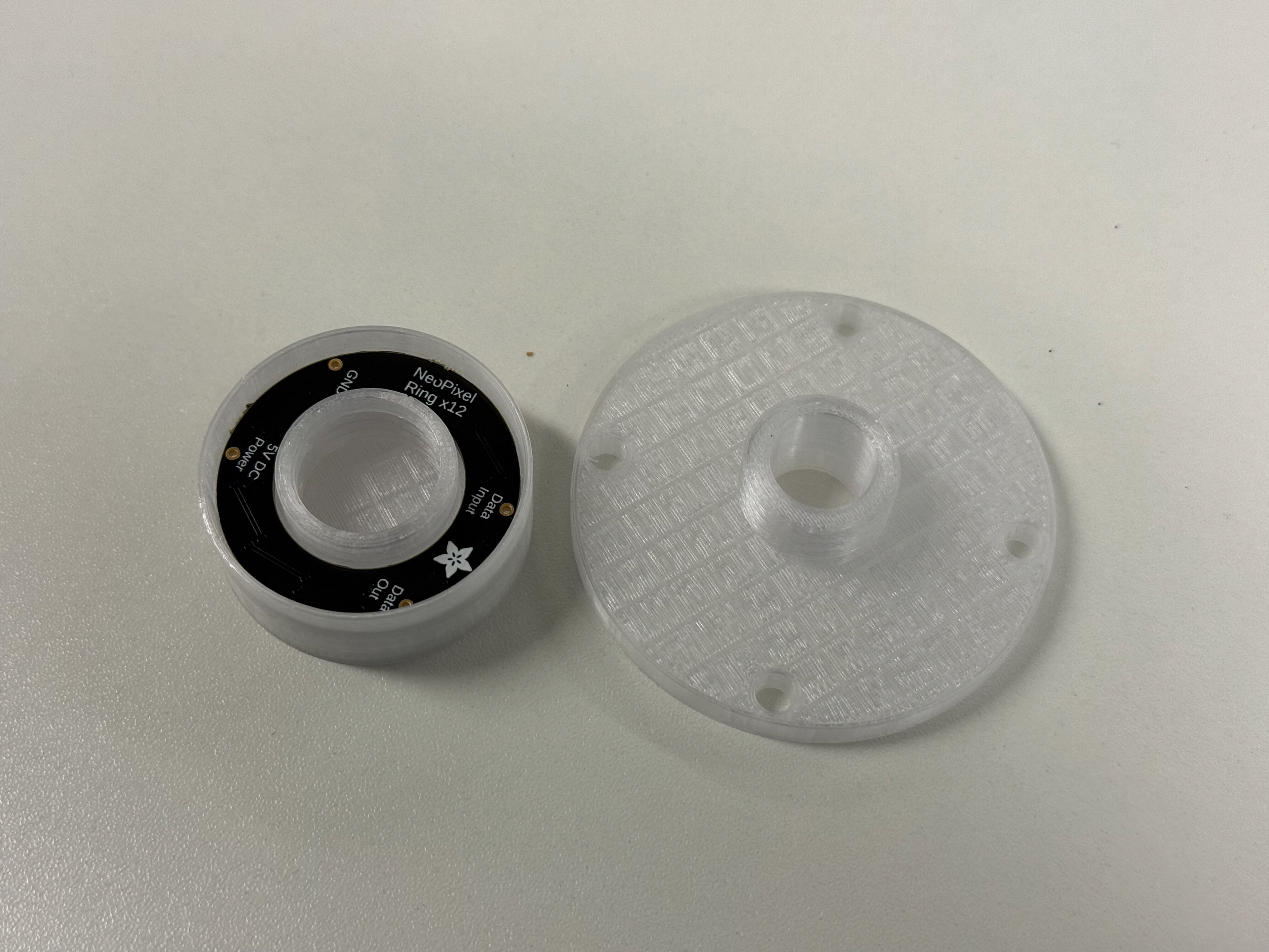
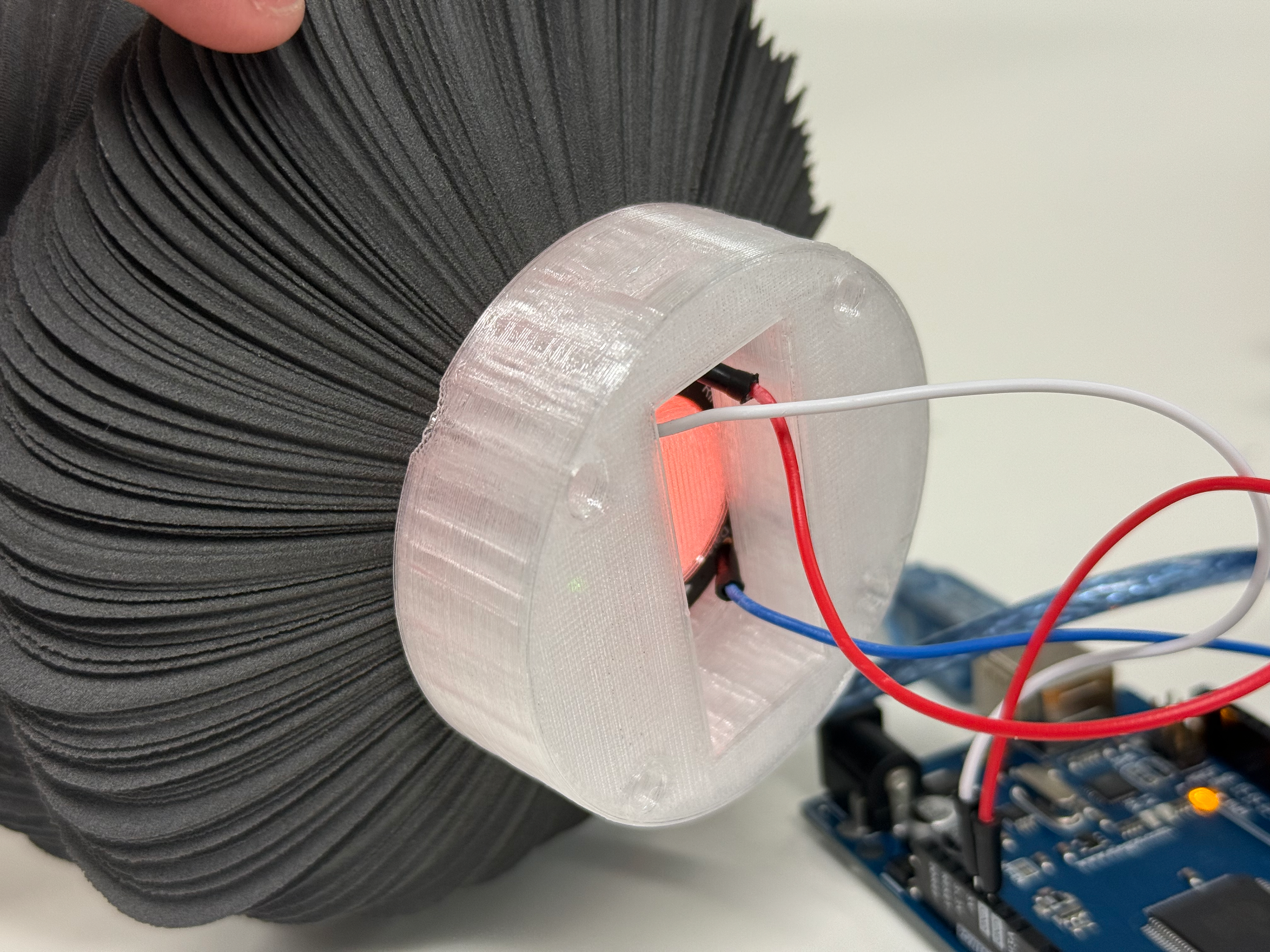
NeoPixel inside the top
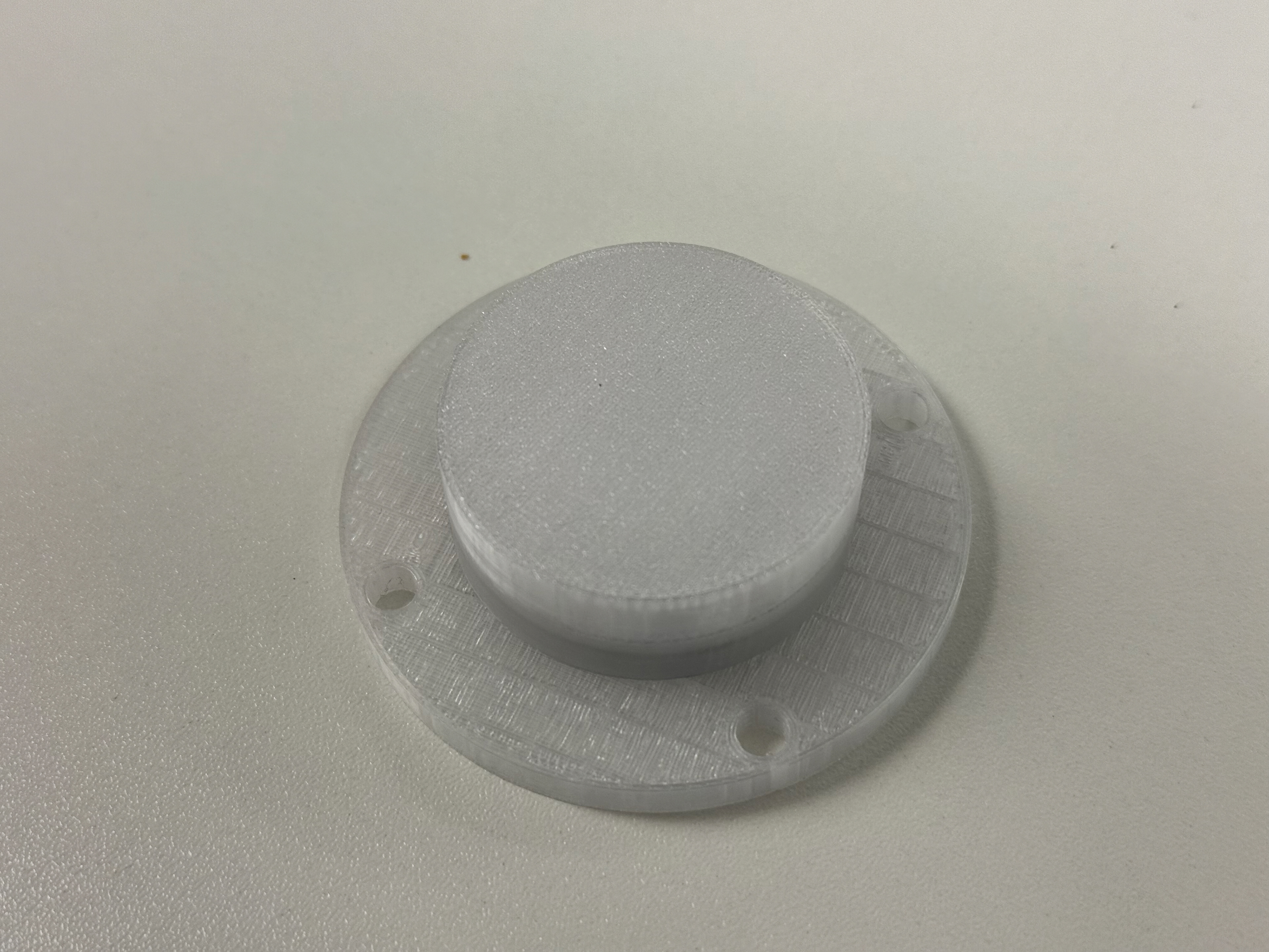
Attached
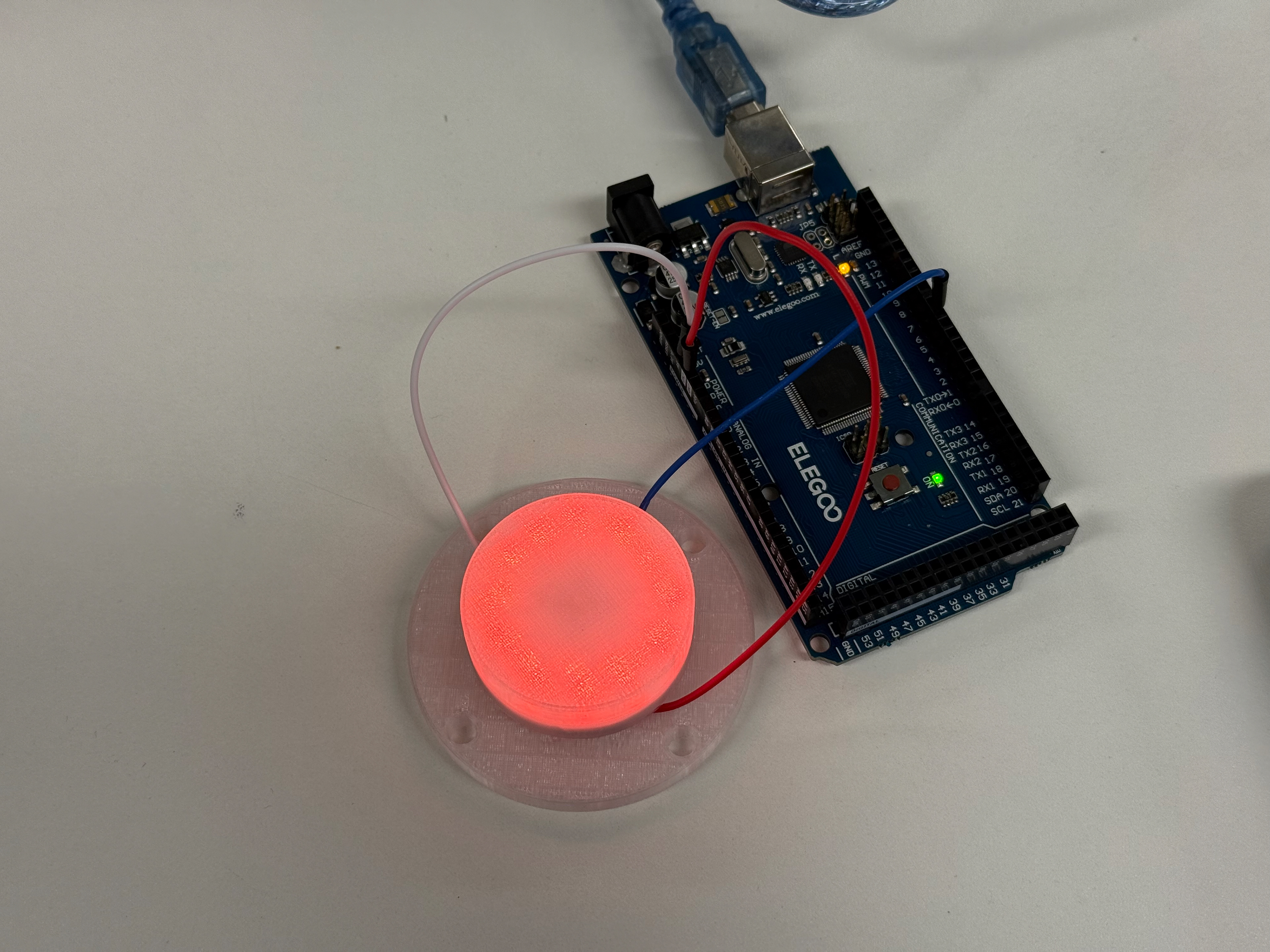
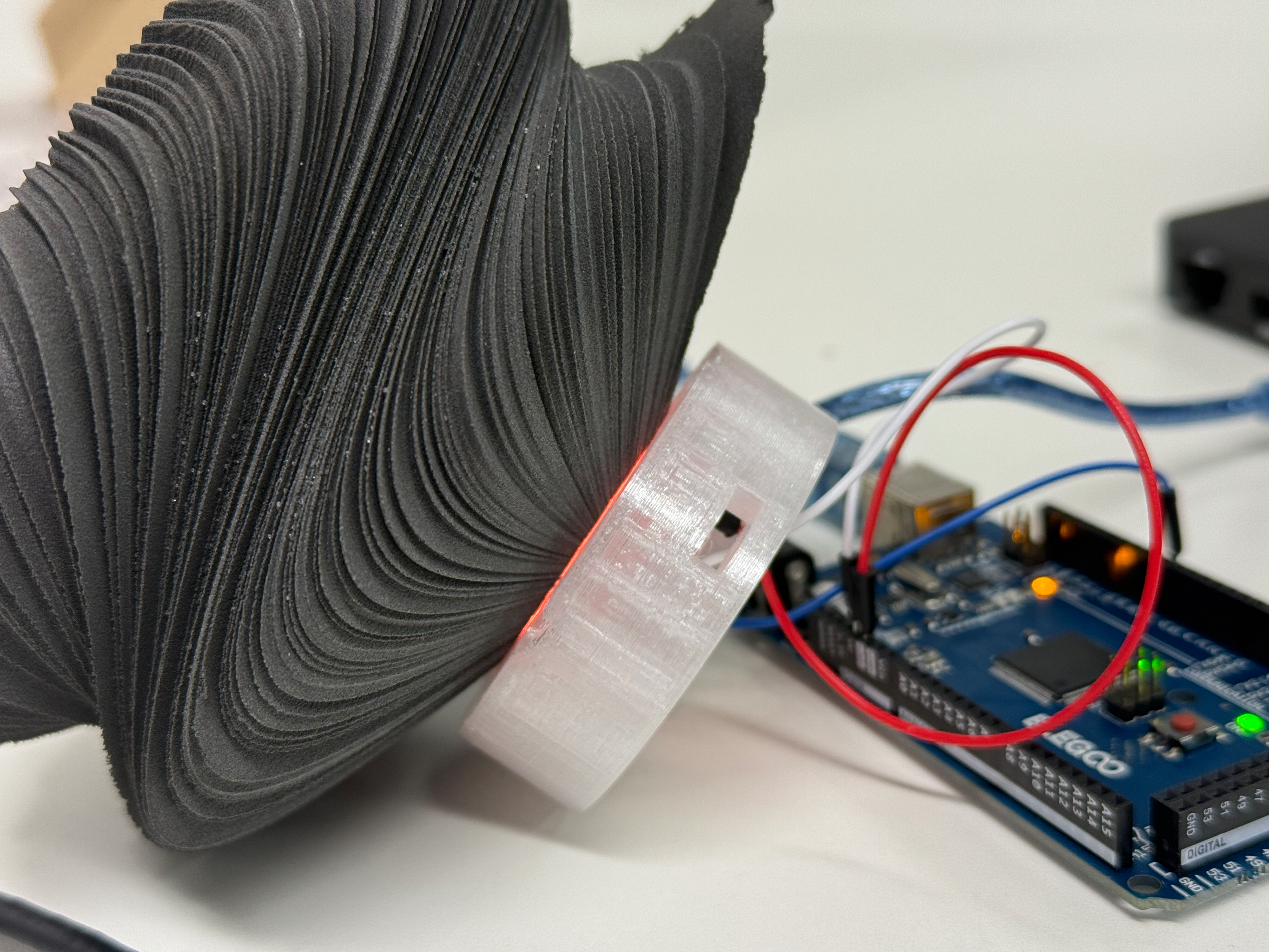
Connected to Elegoo
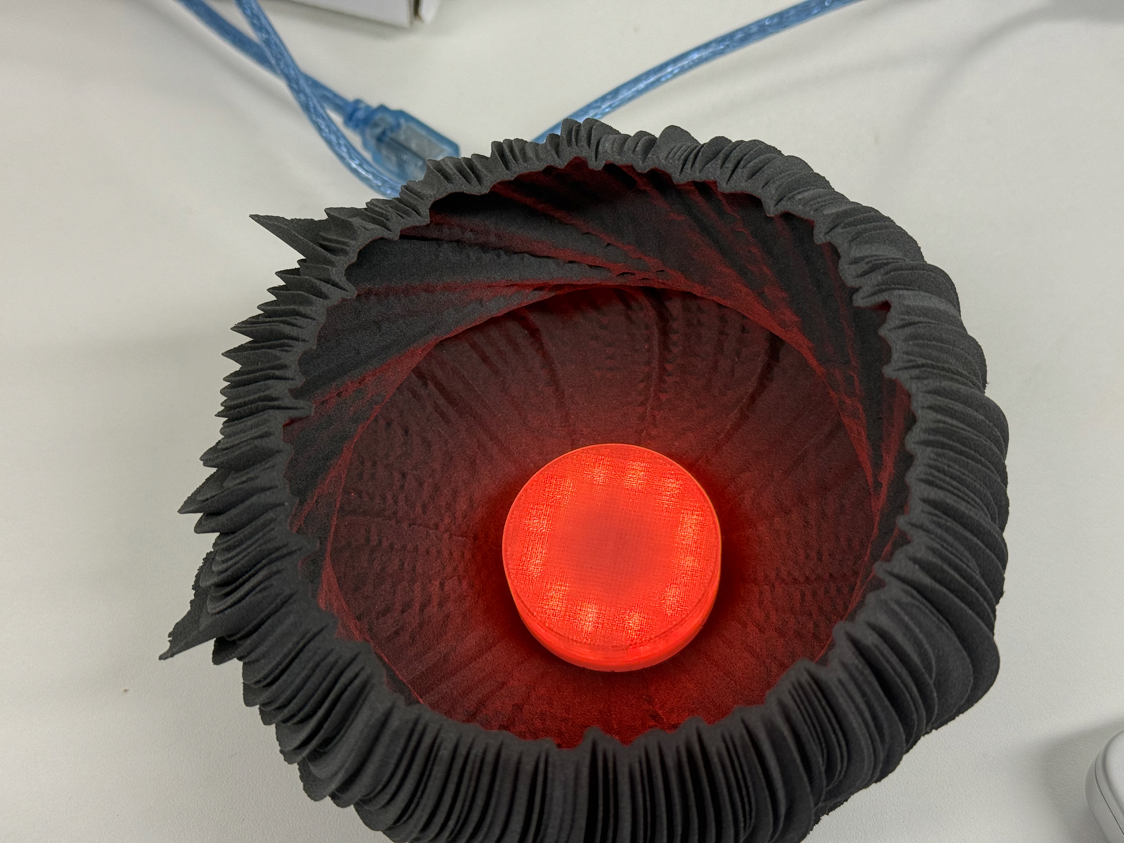
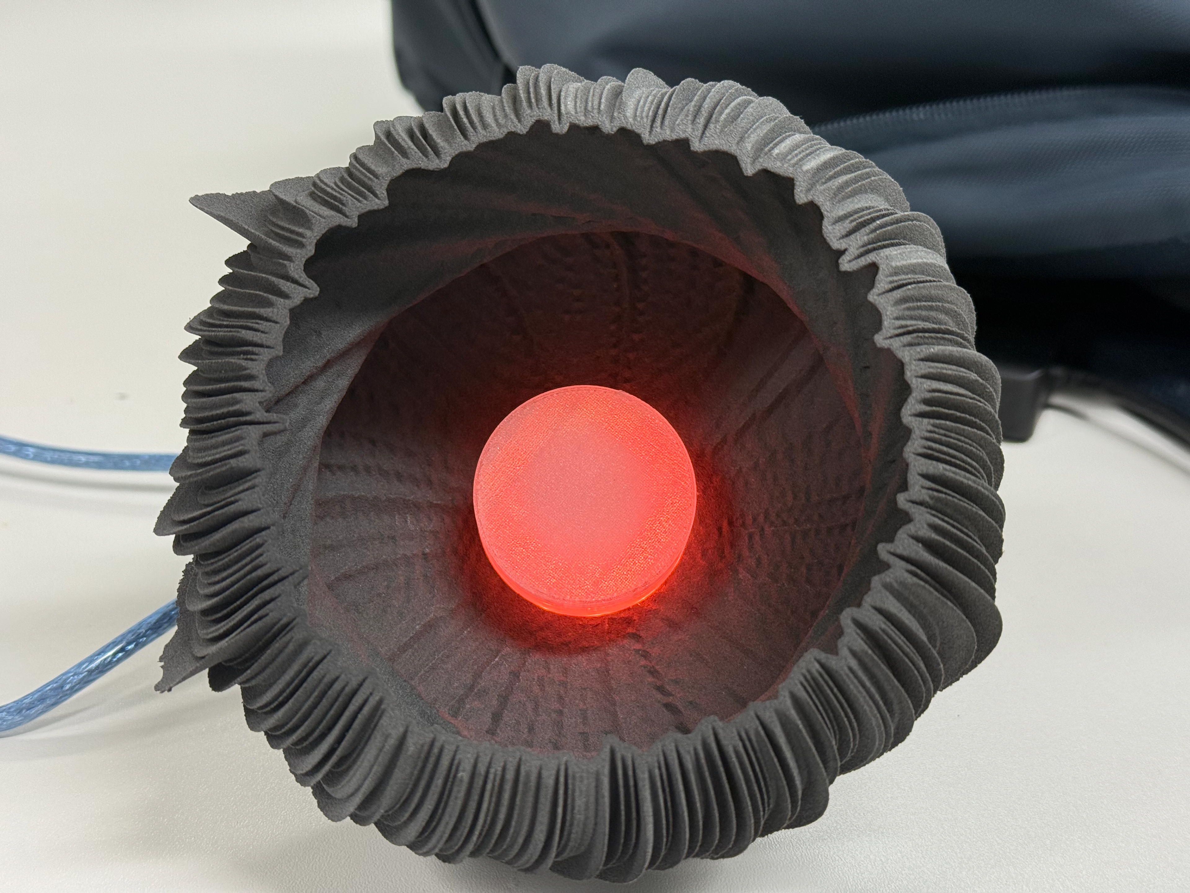
Inside the object
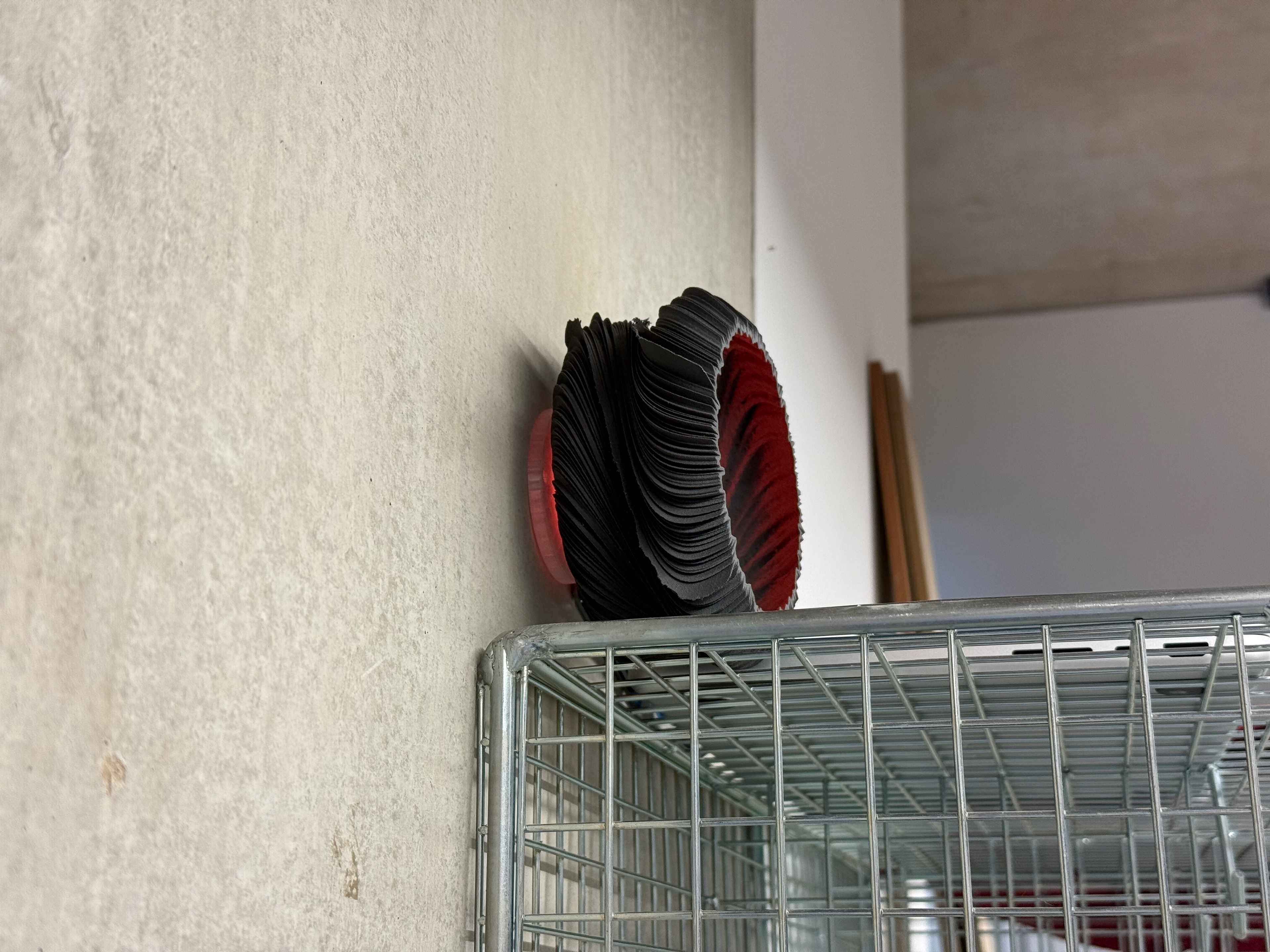
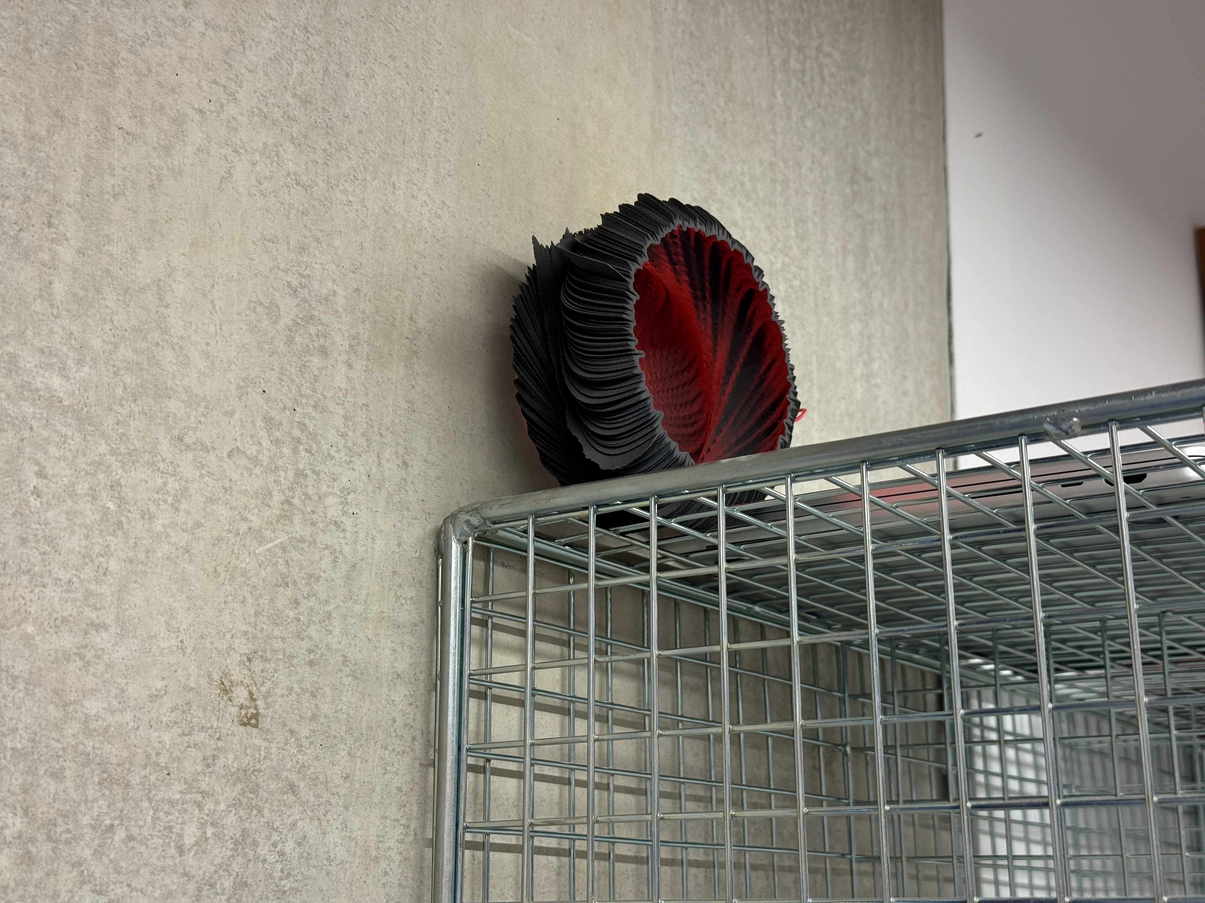
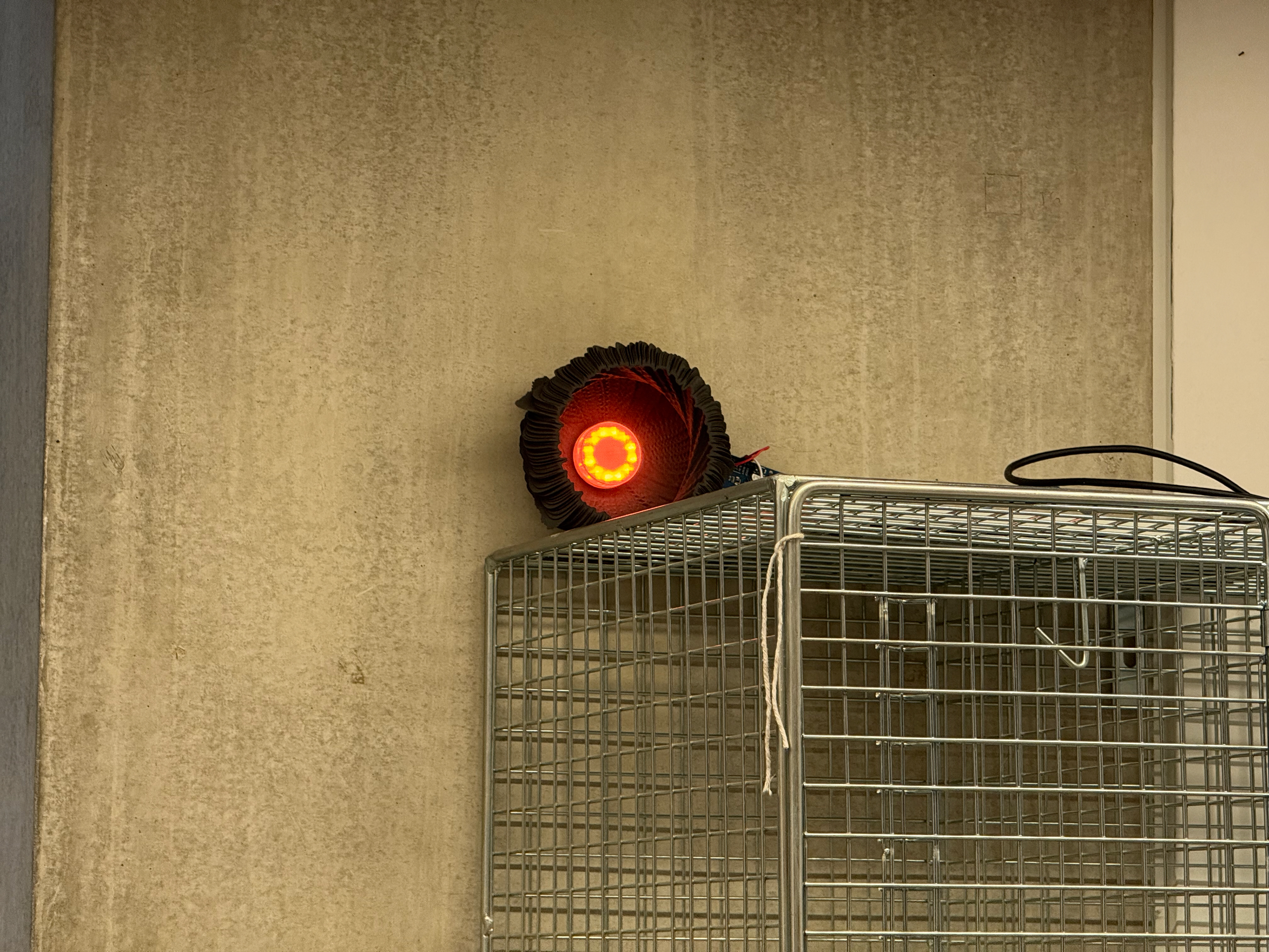
Mounted on a concrete wall
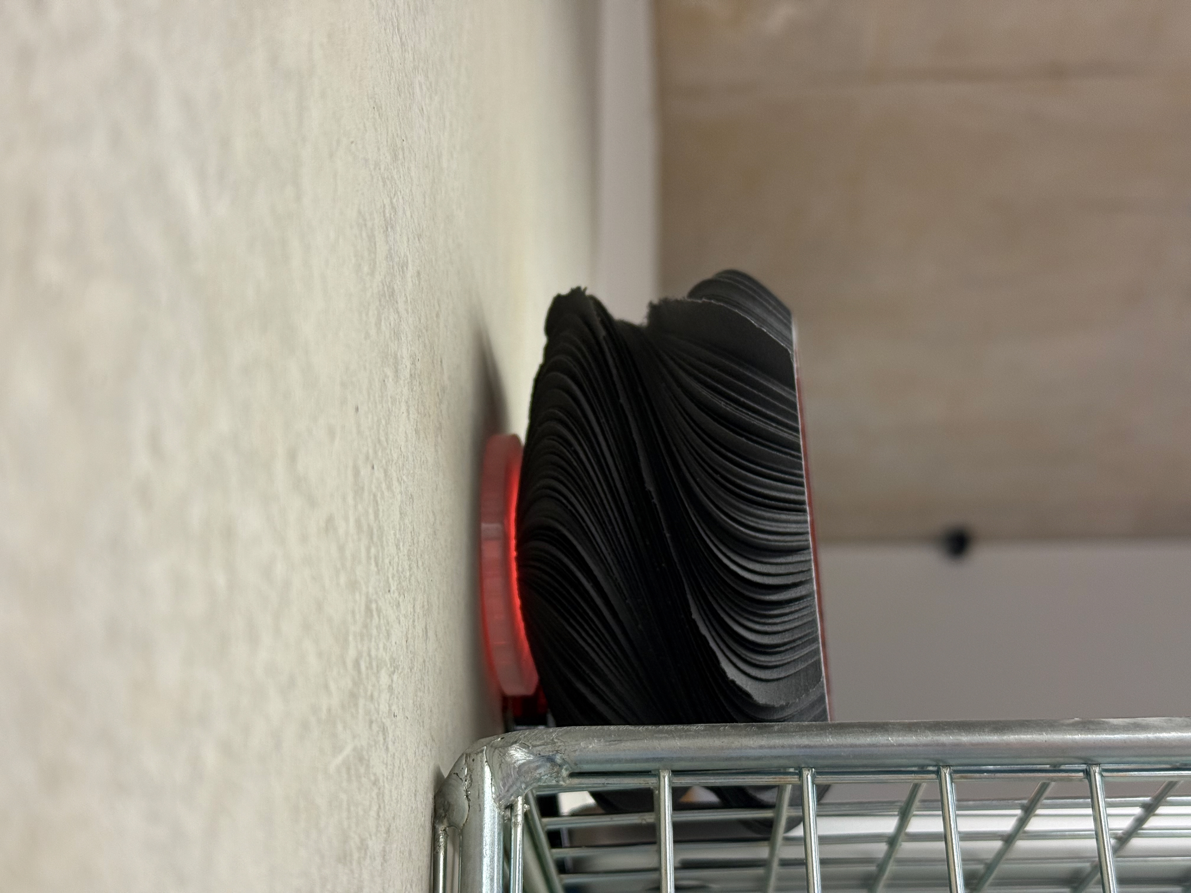
Dark room side view
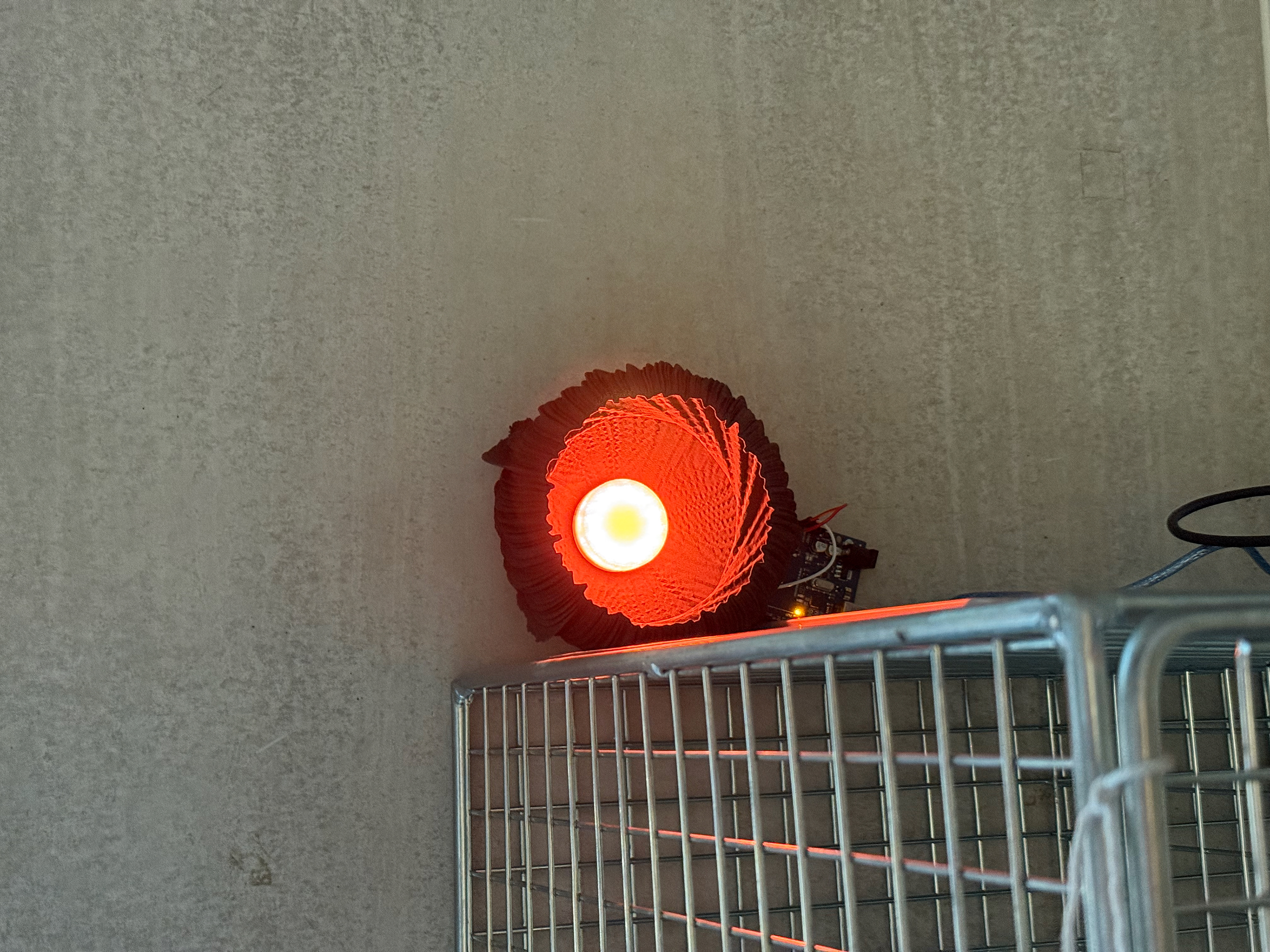
Dark Room front view
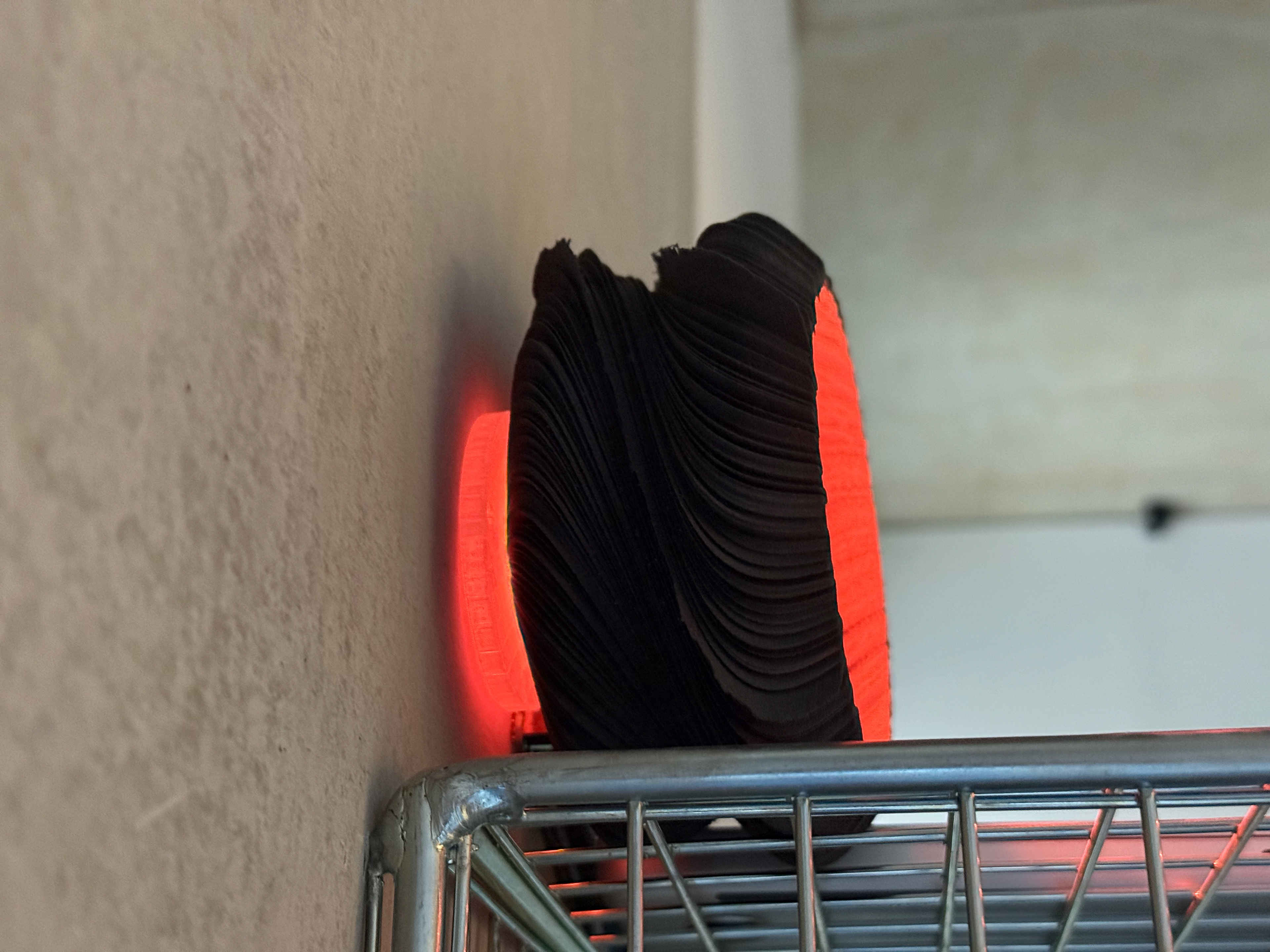
Light on side view
Light on side/front view
Light room front view
Mount Development
Neopixel relocation
By having the NeoPixel inside the top part, it poses some issues. The main issue is that when screwing the cap on, it causes the wiring to twist and potentially become loose, making it harder to install. The second issue is that the cap is quite large, causing the cap to protrude far into the object, which draws the viewer into the lighting aspect rather than lighting the interior of the object up.
NeoPixel in the Mount
Side profile
Top View
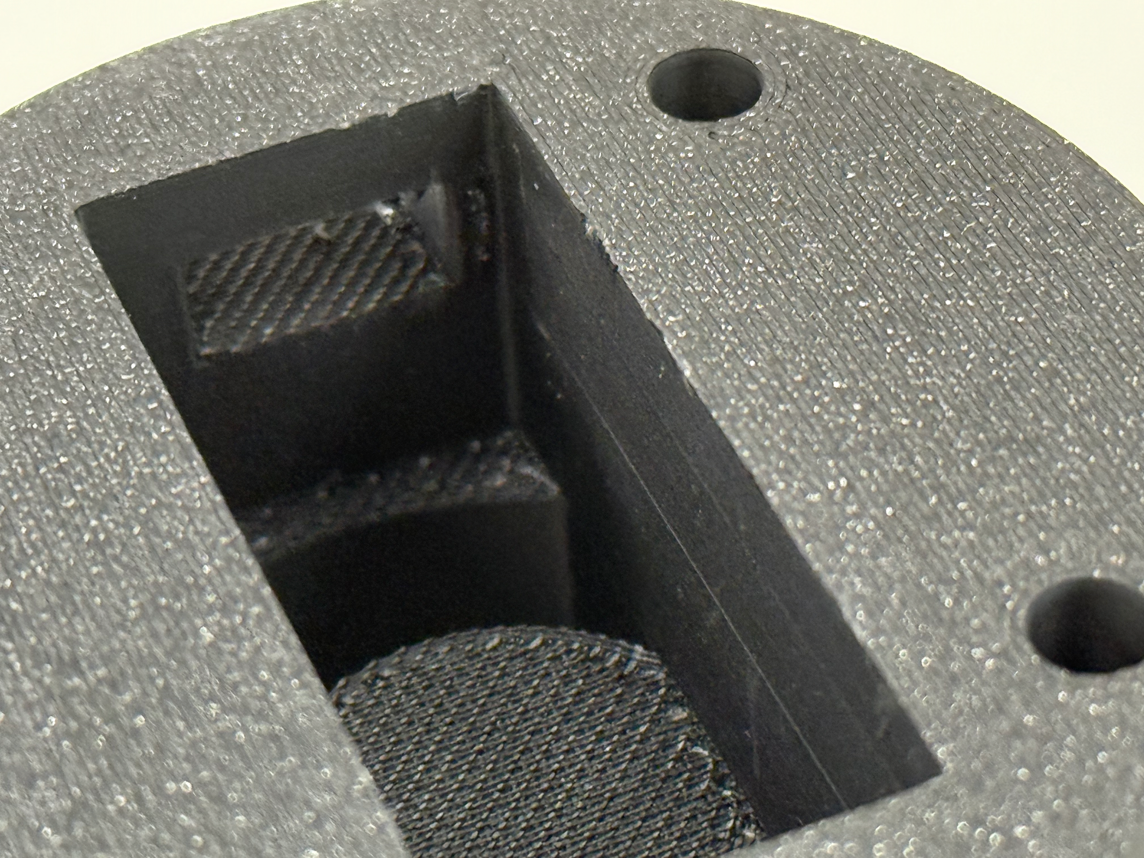
The only place to relocate the NeoPixel was inside the mount itself. Within Fusion, I extruded out my mount and created a cutout using the dimensions of the NeoPixel, leaving enough room for wires to run out the back to the Arduino.
The result was far better than I thought it would be; the difference between in the lens and in the mount is not noticeable but is significantly easier to mount.
The next step will be to create enough room for a smaller Arduino (or similar) to fit in as well as having enough room for wiring.
Final Mounting Design
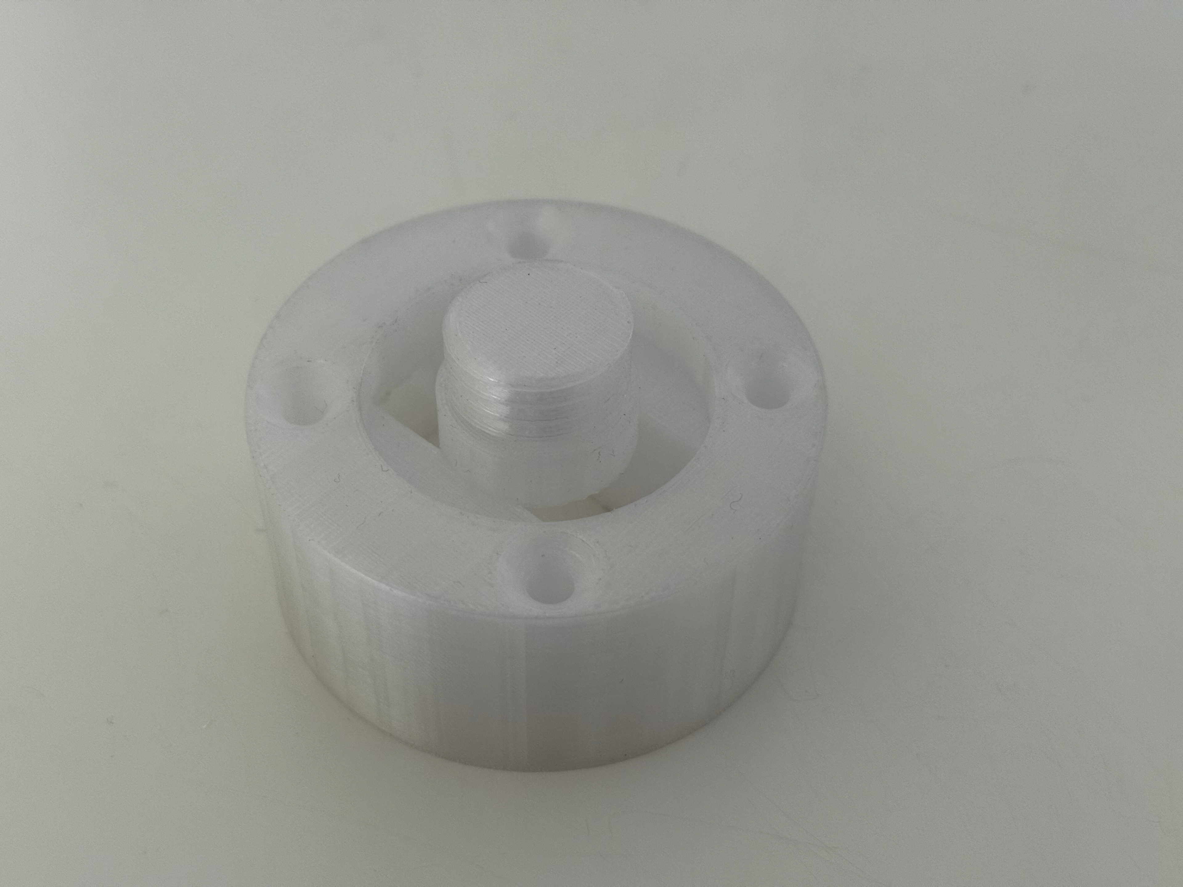
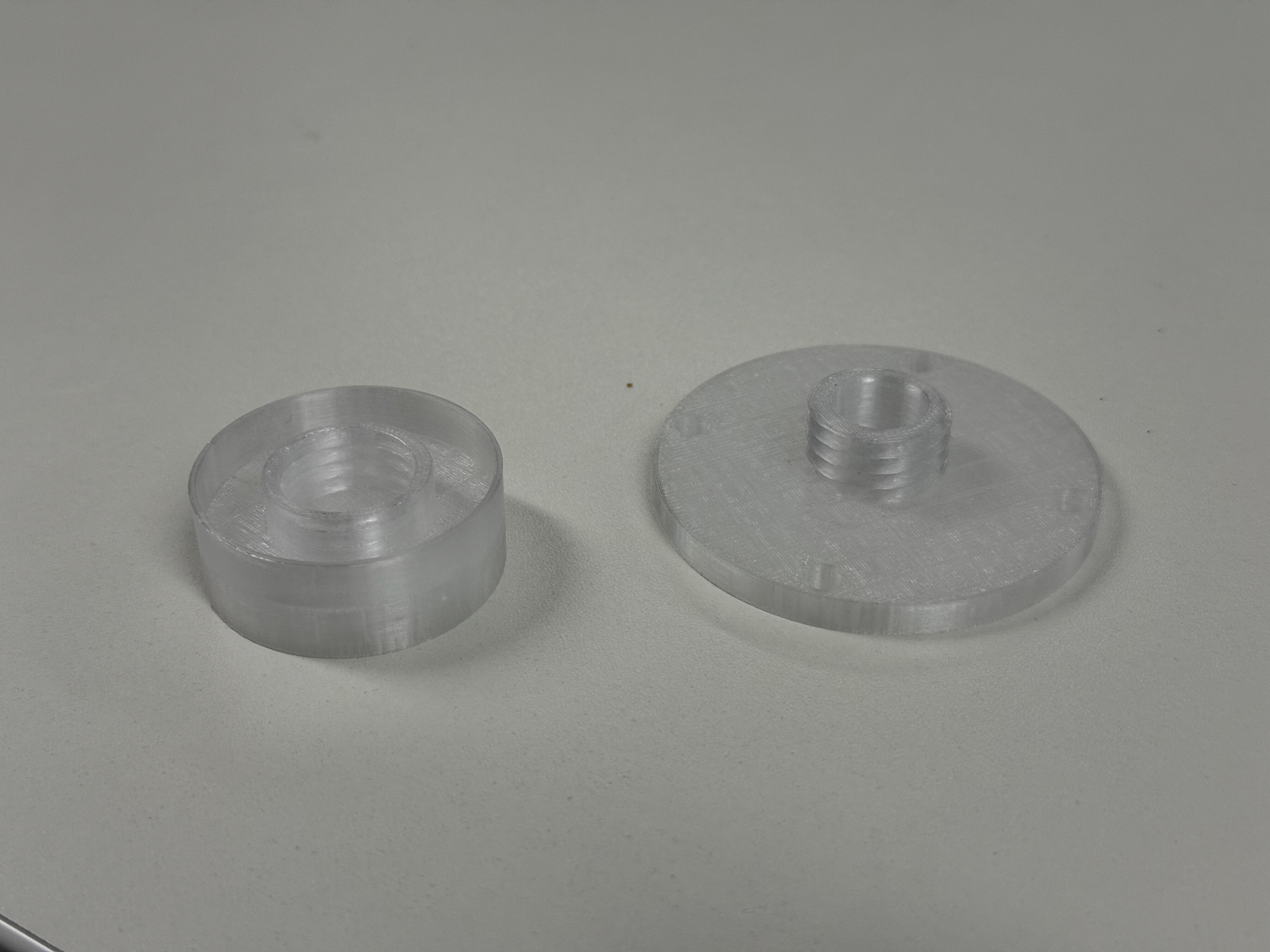
Base for NeoPixel and Seeeduino
You can see the screw section sits directly onto of the hole for the Seeeduino
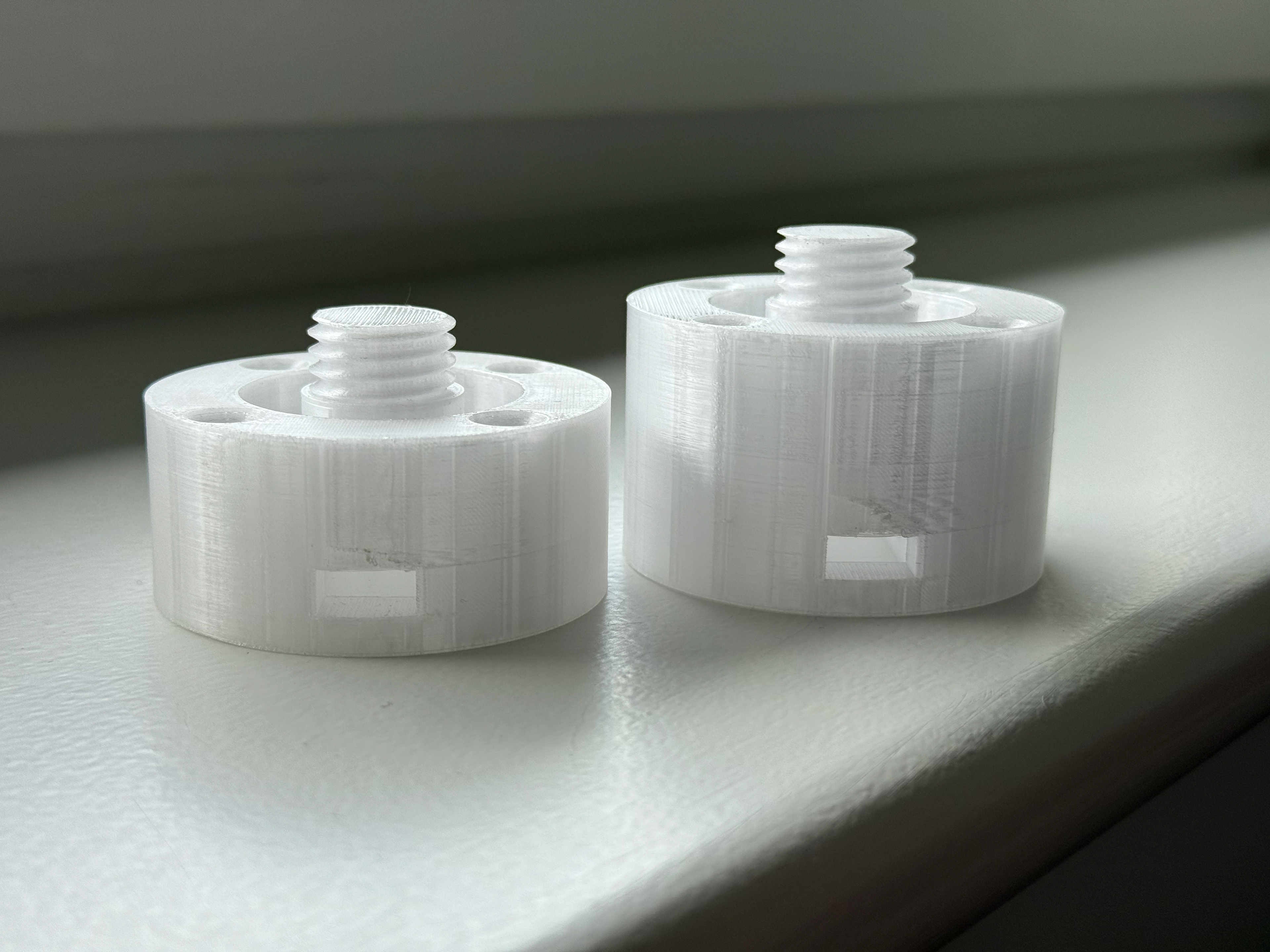
The differences between to two
The difference underneath - allows for room to wire
I started by extruding the base to accommodate the Seeduino Nano (a cheaper version of Arduino Nano). However, this left no room for wiring as the Seeduino was sitting directly below the NeoPixel. I also noticed that the screw sat on top of the rest of the mount, which didn't feel very strong, and with a lot of twist motion I feel like it would break very easily, so I then further extruded that section to add more structural integrity.
This worked very well; it allows for room for wiring whilst keeping all the components secure. This design is now final; I just need to print it in the correct colour.
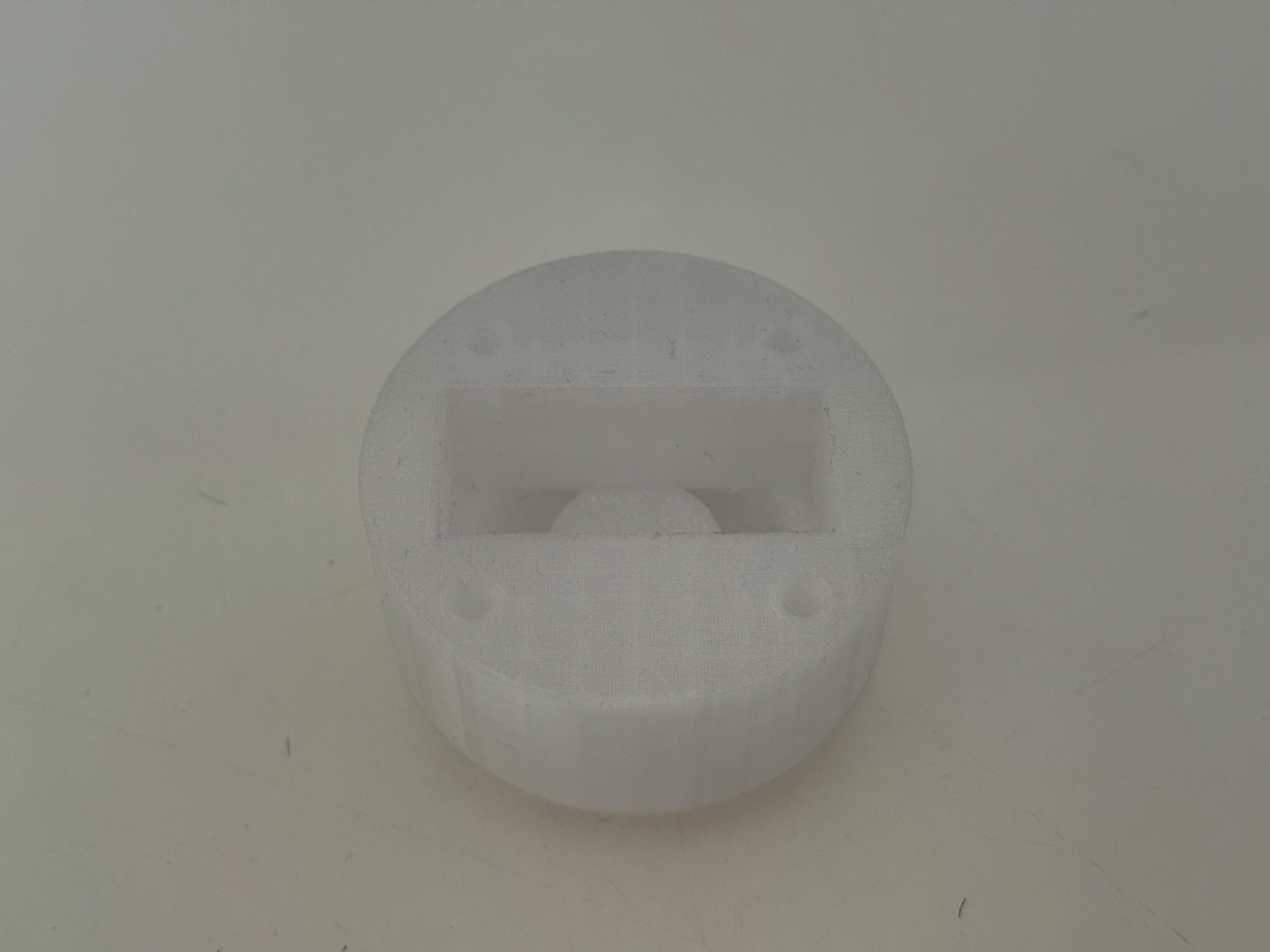
Just the mount
The screw and the ring for the NeoPixel
Hole for the Seeeduino Nano
Cut out for the USB-C cable
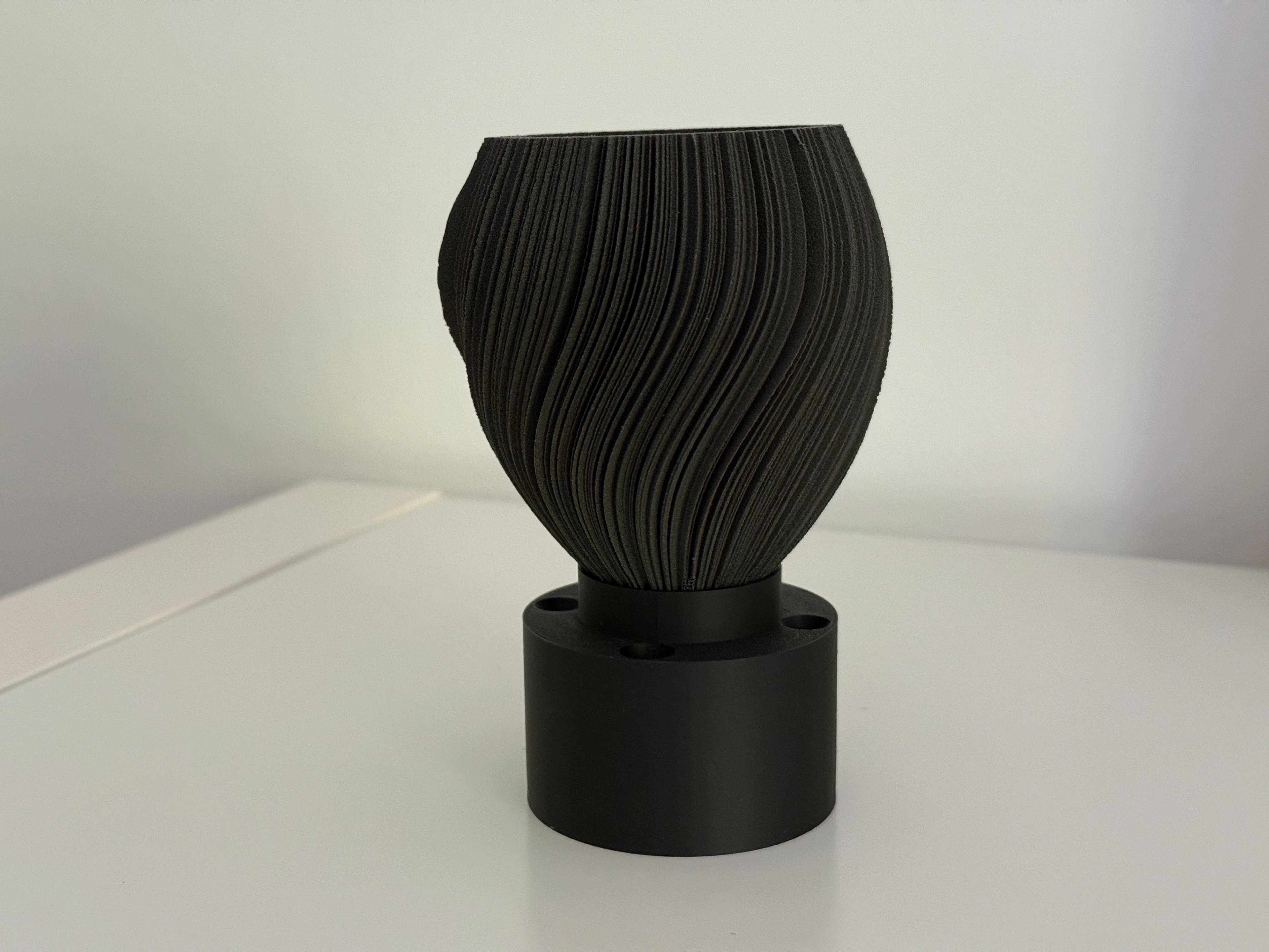
Once the design was finalised, I bought "PLA Matte - Charcoal" to match the colour of the nylon prints, which makes it look more professional as well as keeping the viewer’s attention on the object rather than the mount.
Day 351 Mounting Design
Day 351 is the smallest of all of them, which has a problem regarding the NeoPixel. The base is too small and, as a result, the ring doesn't illuminate the inside, only the outside. To fix this, I simply need to lift the object further above the light to ensure light can pass through. I would use a smaller ring, but they don't sell them. I could scale the object up, but in order for the ring to fit, the object would be very big, completely removing the whole meaning behind my project.
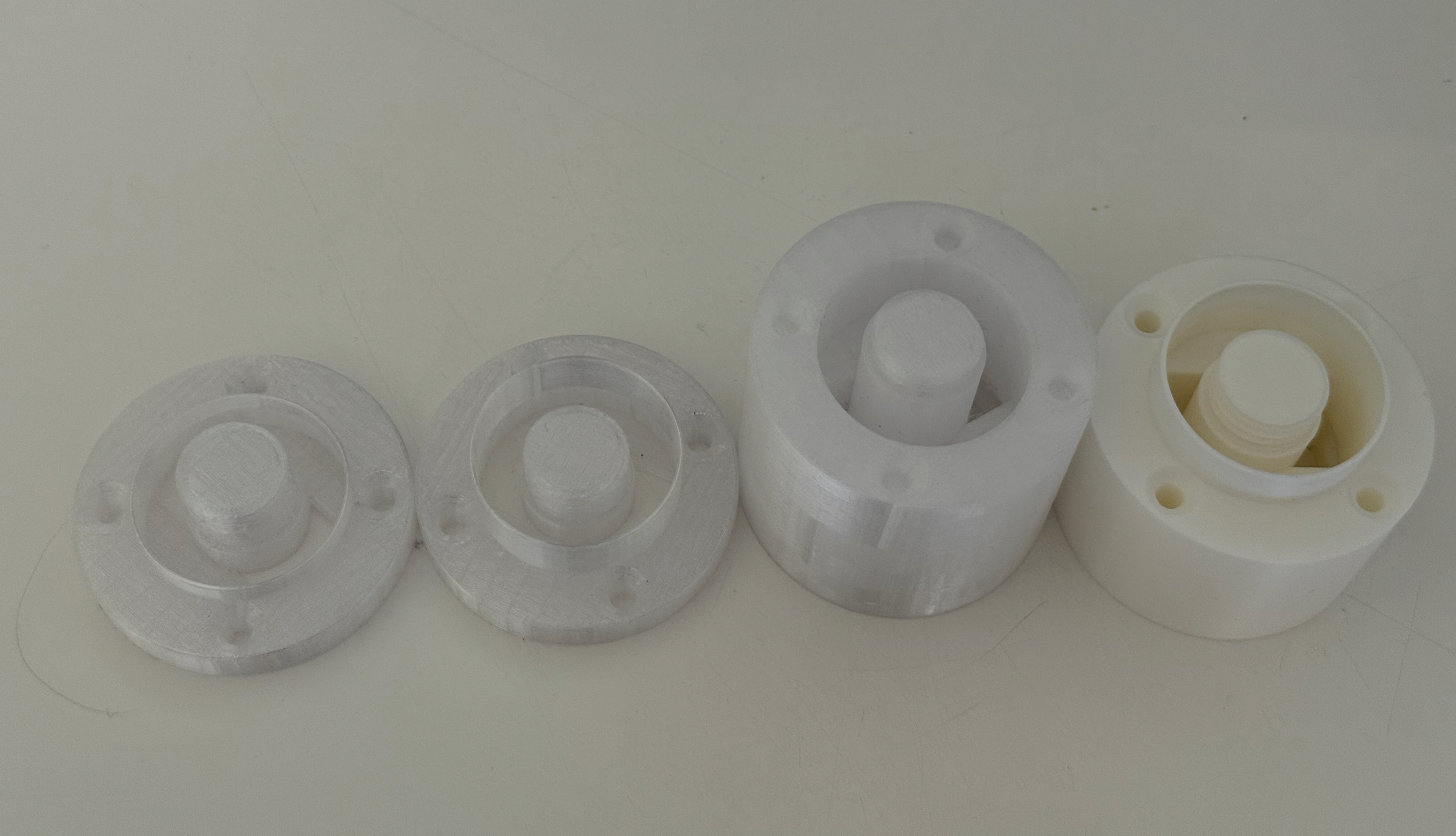
The different versions in order
Sat on the normal mount
On the normal mount, light escapes out and doesn't go into the object
Very dim inside
Sat on it's unique mount
Sat on the final unique mount
Much brighter
Wiring DEMONSTRATION
I decided to record how I’m wiring up my pieces. I first strip the wires as much as possible; this is required because the plastic protective casing is too rigid. From a safety standpoint, it's a 5V connection, so no harm can be caused by doing this, and if the three wires connect, it just doesn't light up, so no issue from a safety perspective. The problem is that it's very fiddly and annoying to do. I have an idea for how I would do the light and mounting solution differently in the future, but that will be outlined elsewhere.
After stripping the wires, I wrap the end around the NeoPixel hole. Then I simply connect the other end to the appropriate connectors on the Seeeduino Nano (GND, 5V, Pin 10), then push the NeoPixel into the mounting and ensure the cables don't touch and are secure.
Mounting test
I found a spare piece of wood that I could screw my mount into and test that the mount would work as I intended. There was no reason for it not to, but I wanted to ensure I hadn't overlooked anything.
Screwed onto offset of wood
Held up vertically, no issues and doesn't move around
Lens Refinement
The Lenses refinement
Prototype
Version 1
Version 2 and 3
Version 4 and 5
Version 6 and 7
Version 8
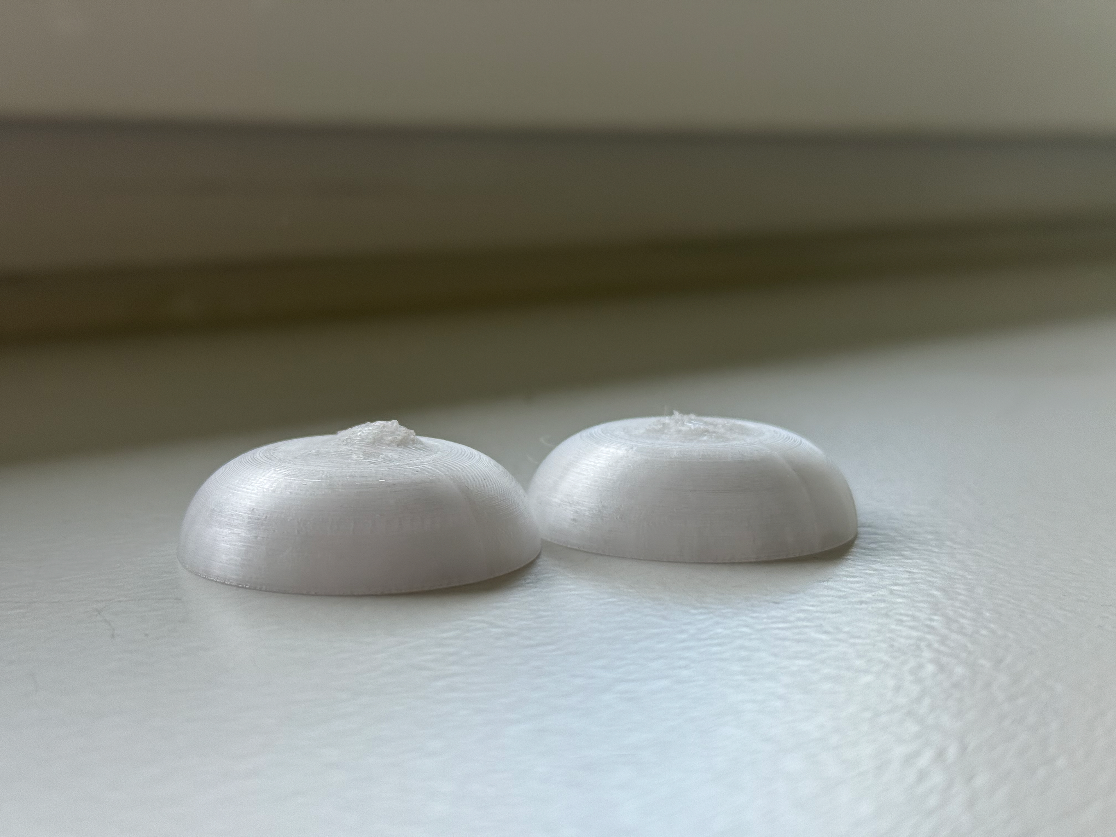
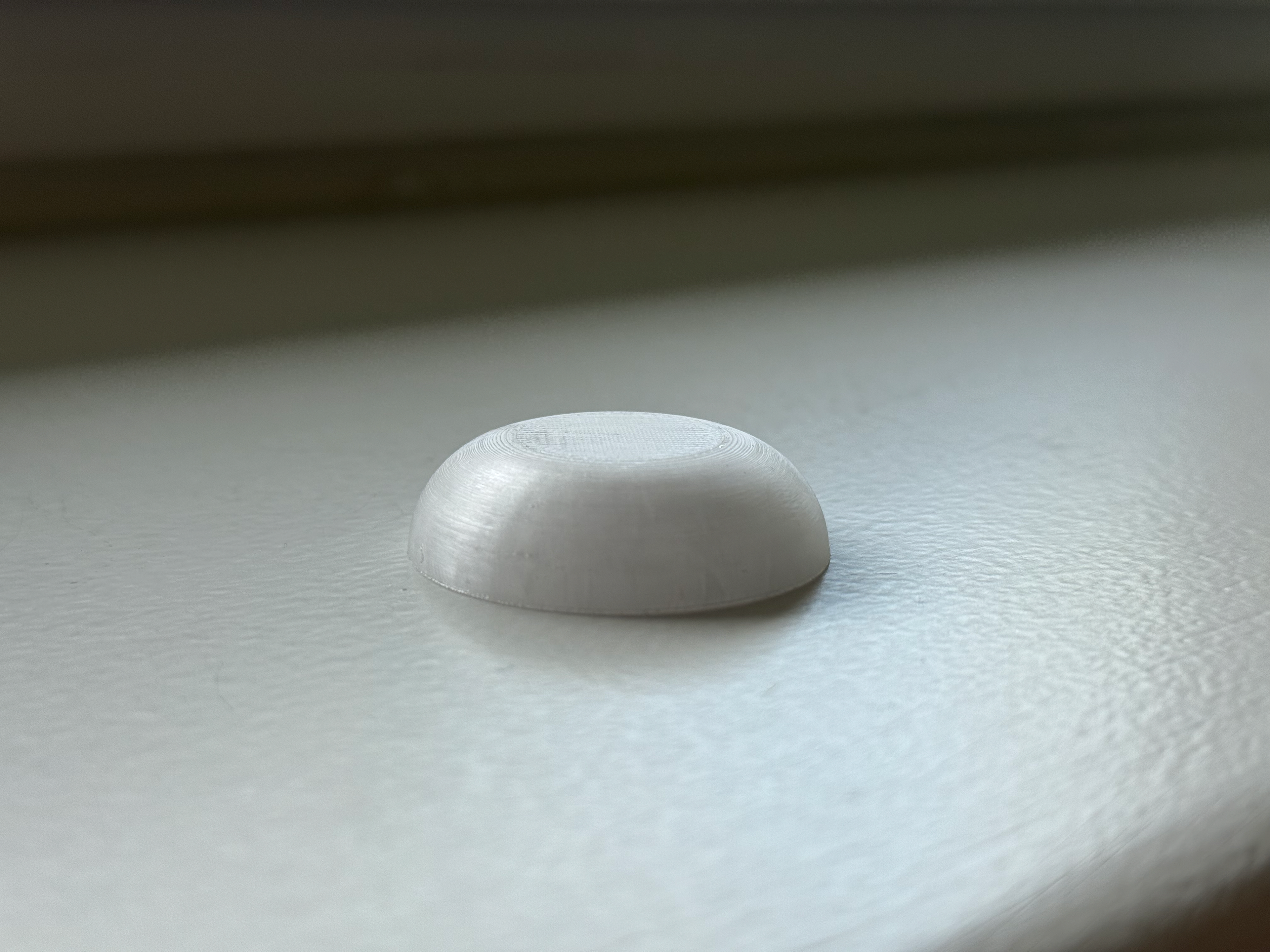
I started out with a very simple shape, just for ease of manufacture. As the idea of the NeoPixel developed, so did the lens. The difference between the prototype and Version 1 is inside; Version 1 has a cut-out of the NeoPixel. At Version 2 and 3, I transferred from the Ultimaker S5 to the Bambu Lab A1 and experimented with a fillet. I was unhappy with the fillet as it was a bit too harsh. By Version 4 and 5, I had removed the NeoPixel from the lens, which allowed me to make them much thinner. I decided to once again try a fillet; this time, I did it on both, one with a larger fillet than the other. This time, I was quite happy with the quality of the larger result. Version 6 and 7 was an experiment with the print quality settings. Version 6 had a "Top Shell Thickness" of 0.8mm while Version 7 had 3mm. This setting tells the printer when to stop printing infill and to print the whole thing. The idea is that it would prevent the light from coming out the top directly and force the light to disperse out the sides. The issue with these two is the tops; this occurred because I didn't add a support layer. The result of the various thicknesses was that the light dispersed more evenly in Version 7, but the overall dispersion out the top was the same, although this was probably from the hole in the top. For Version 8, I added supported layers and stuck with the 3mm Top Shell Thickness.
0.2mm hotend
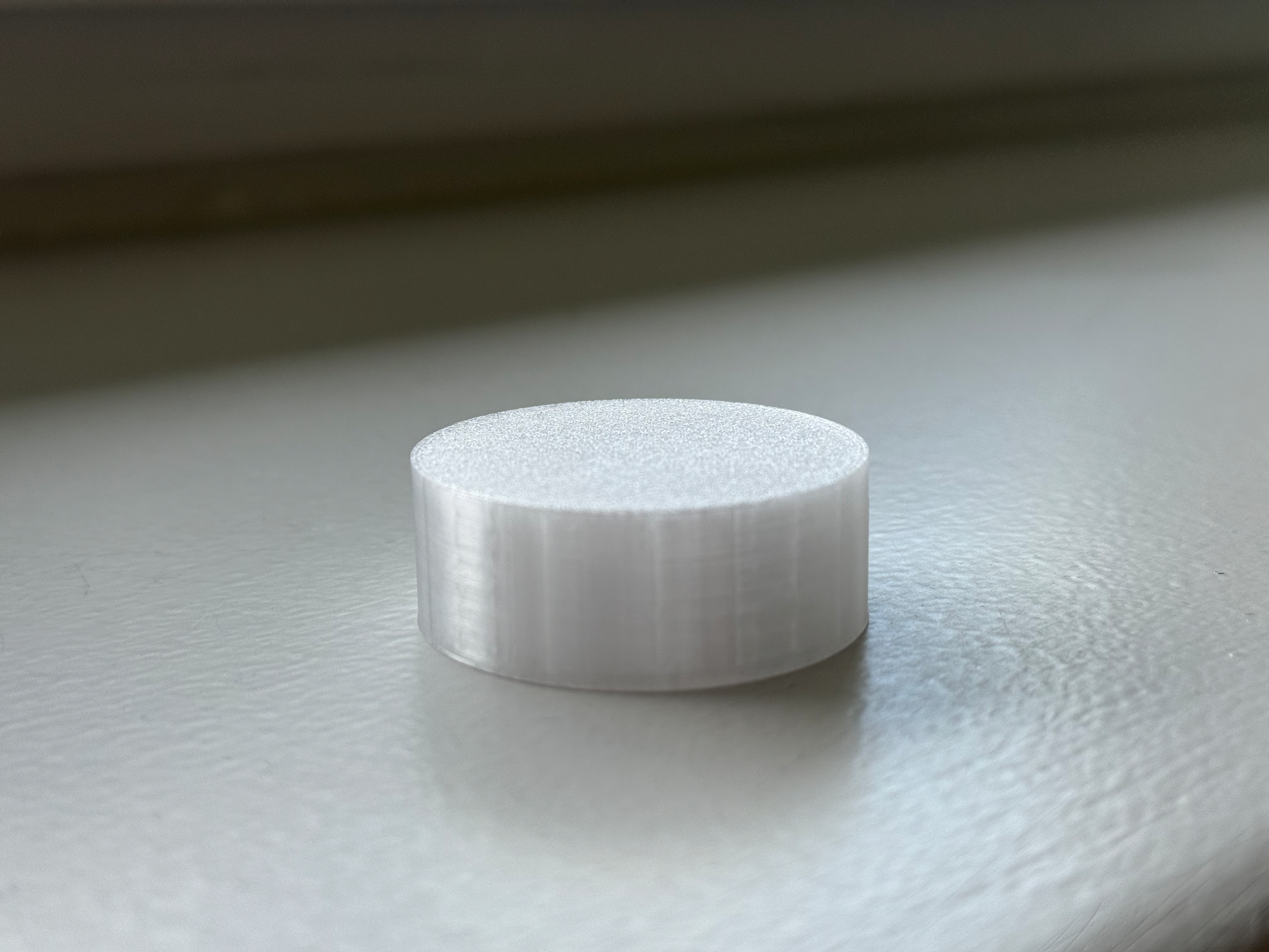
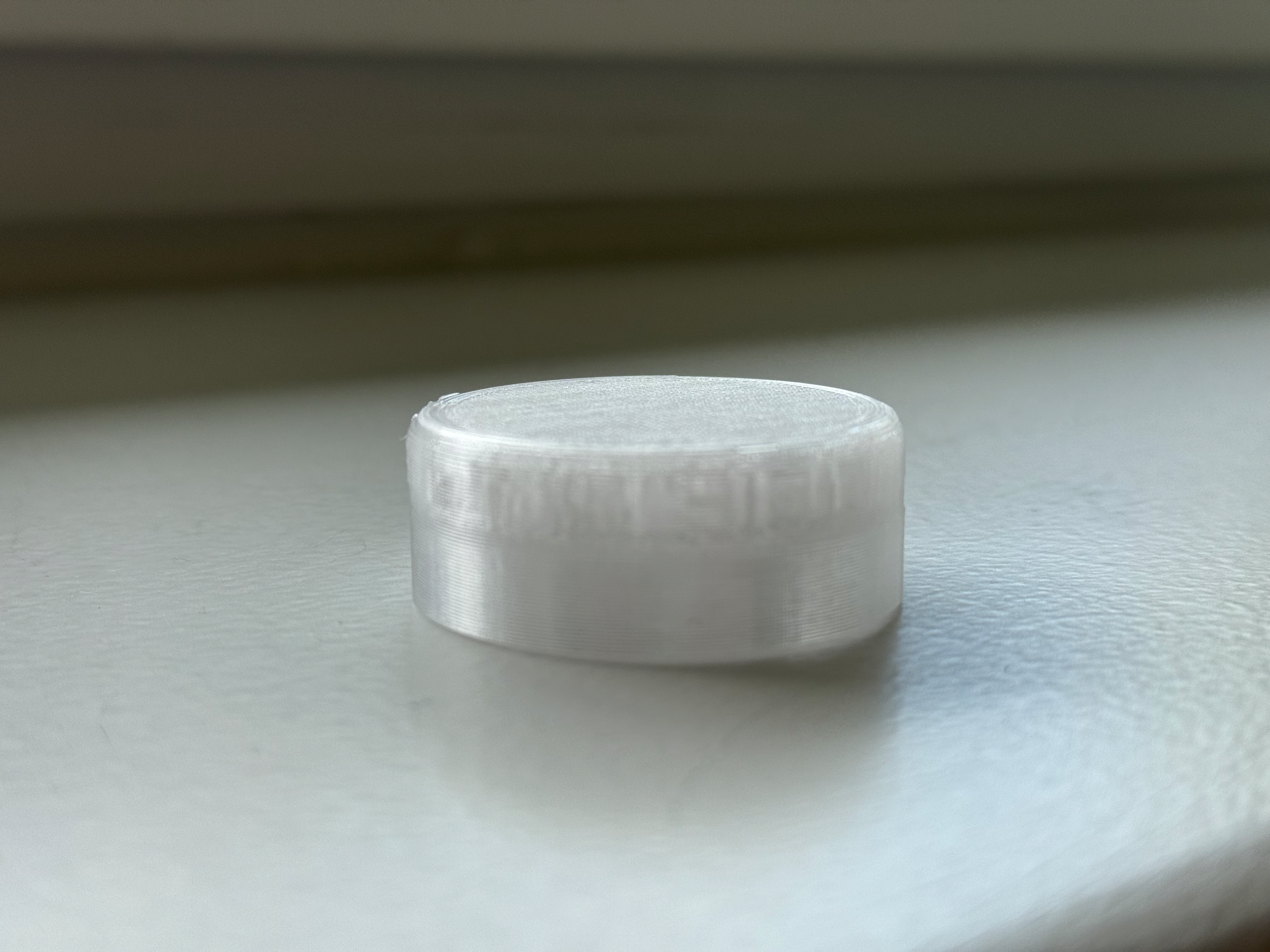
Version 2 and 3 and onwards, I used the Bambu Lab 0.4mm Hotend with the Bambu Lab Textured PEI Plate. However, I wasn't happy with the quality it provided, especially around the filleted edges, so I decided to purchase a 0.2mm hotend and the Smooth PEI plate, both of which would provide a smoother surface.
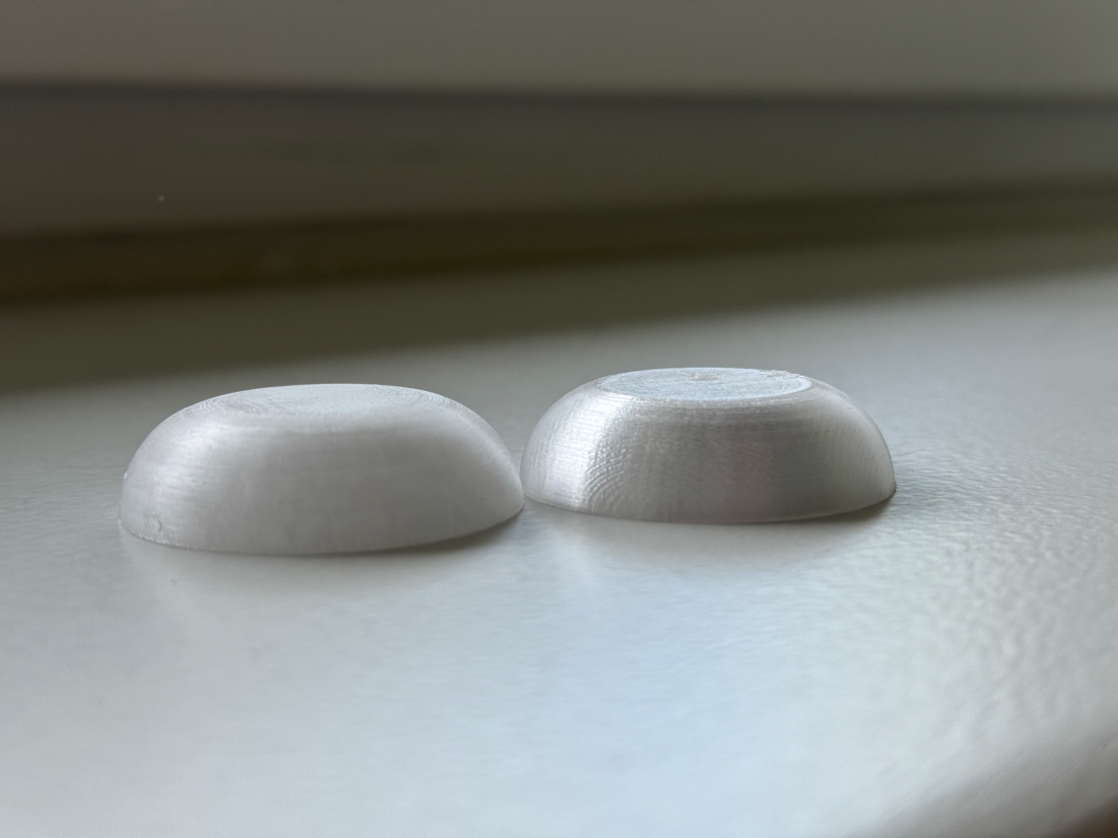
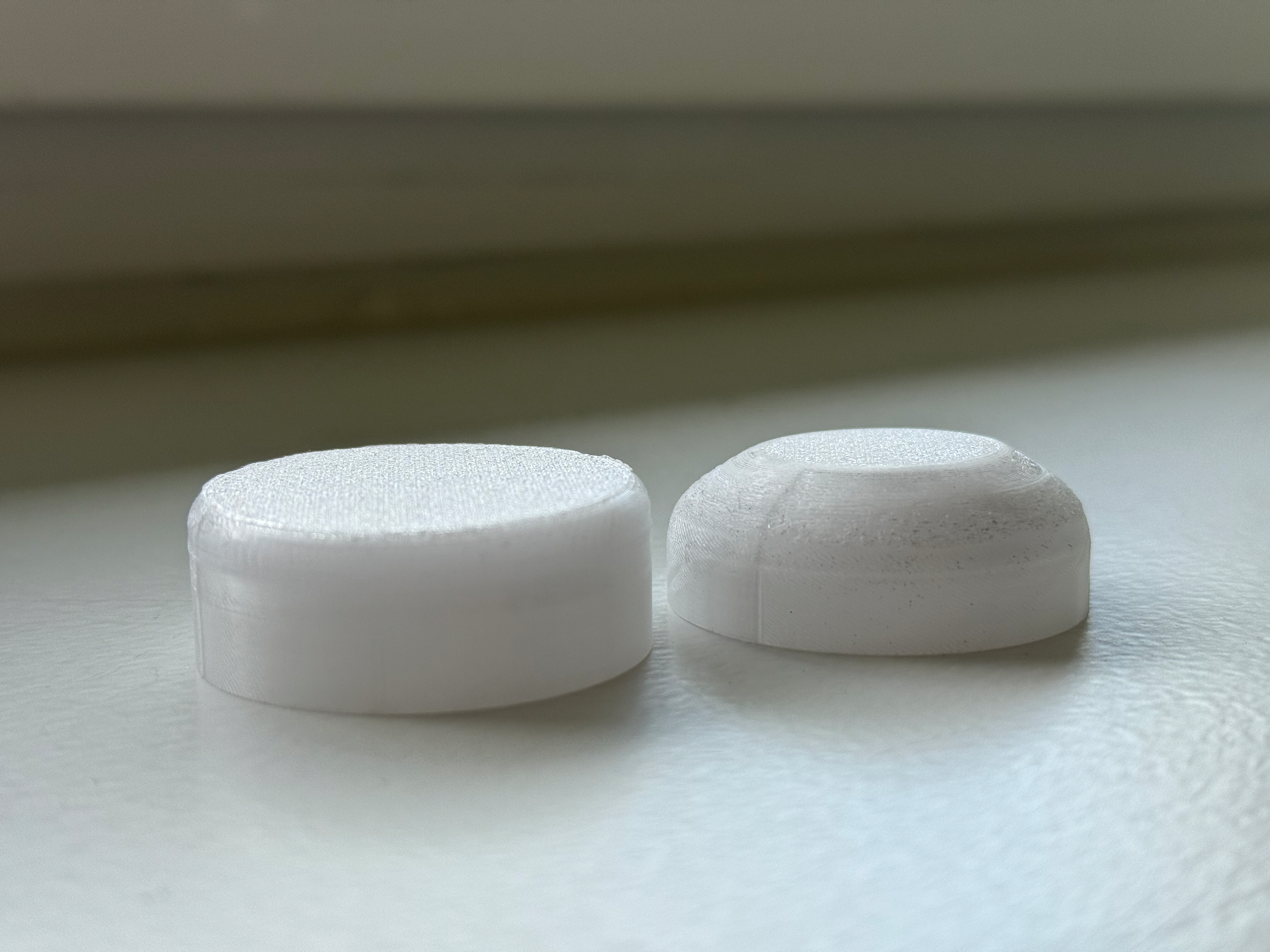
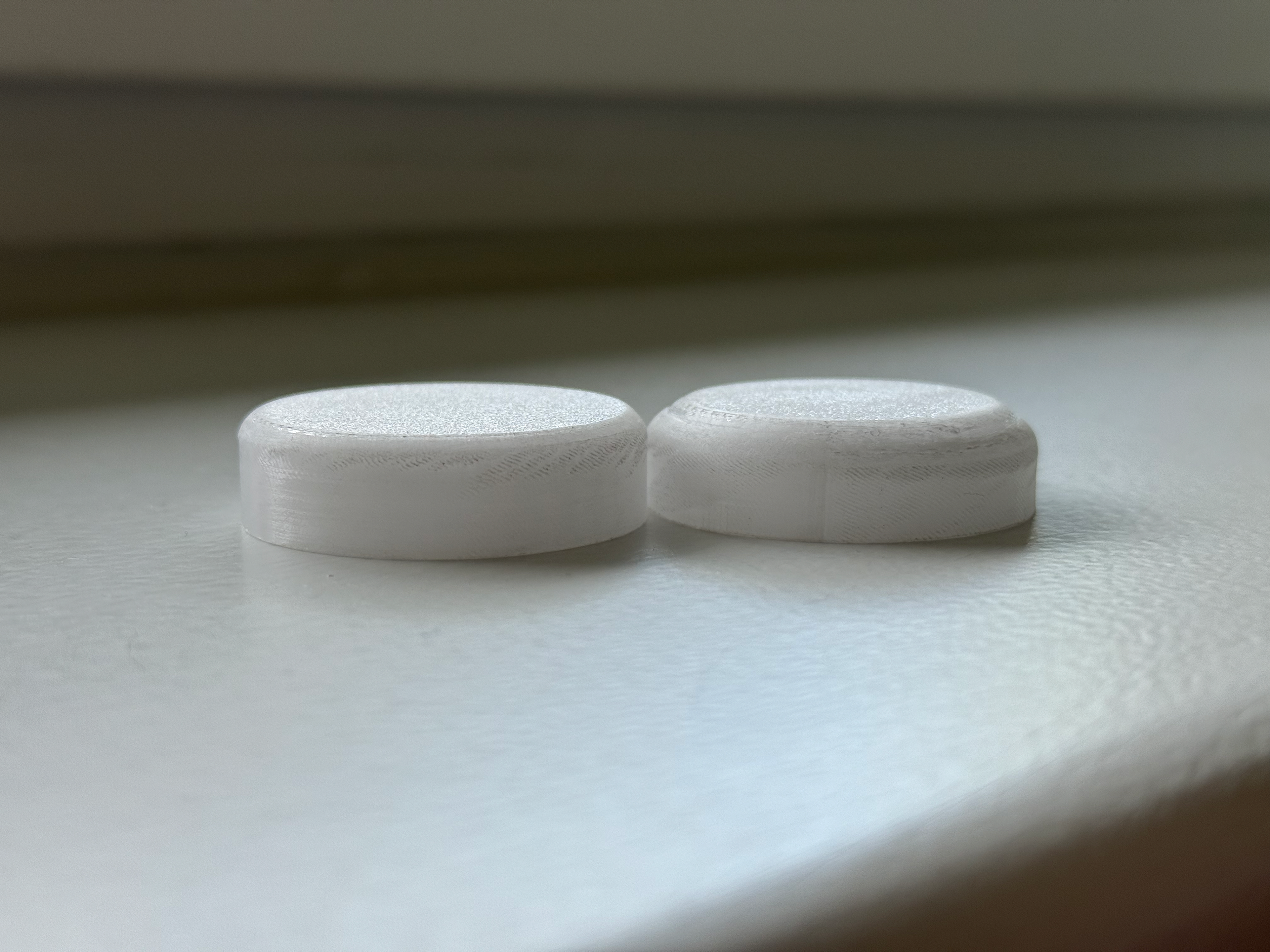
On the left is the 0.4mm print and on the right is the 0.2mm print. The difference is clear, and using 0.2mm was a smart move. Since these parts are layered, regardless of how much sanding is done on the outside, you will always be able to see the print lines. By using a 0.2mm nozzle and the 0.06mm BambuStudio layer height preset, I get the smoothest possible print, making sanding unnecessary. Regardless, sanding will make the feeling nicer when mounting, but it will reduce grip, which is actually needed for mounting. I will have to look into this and see if sanding will provide a net positive.
Resin Print
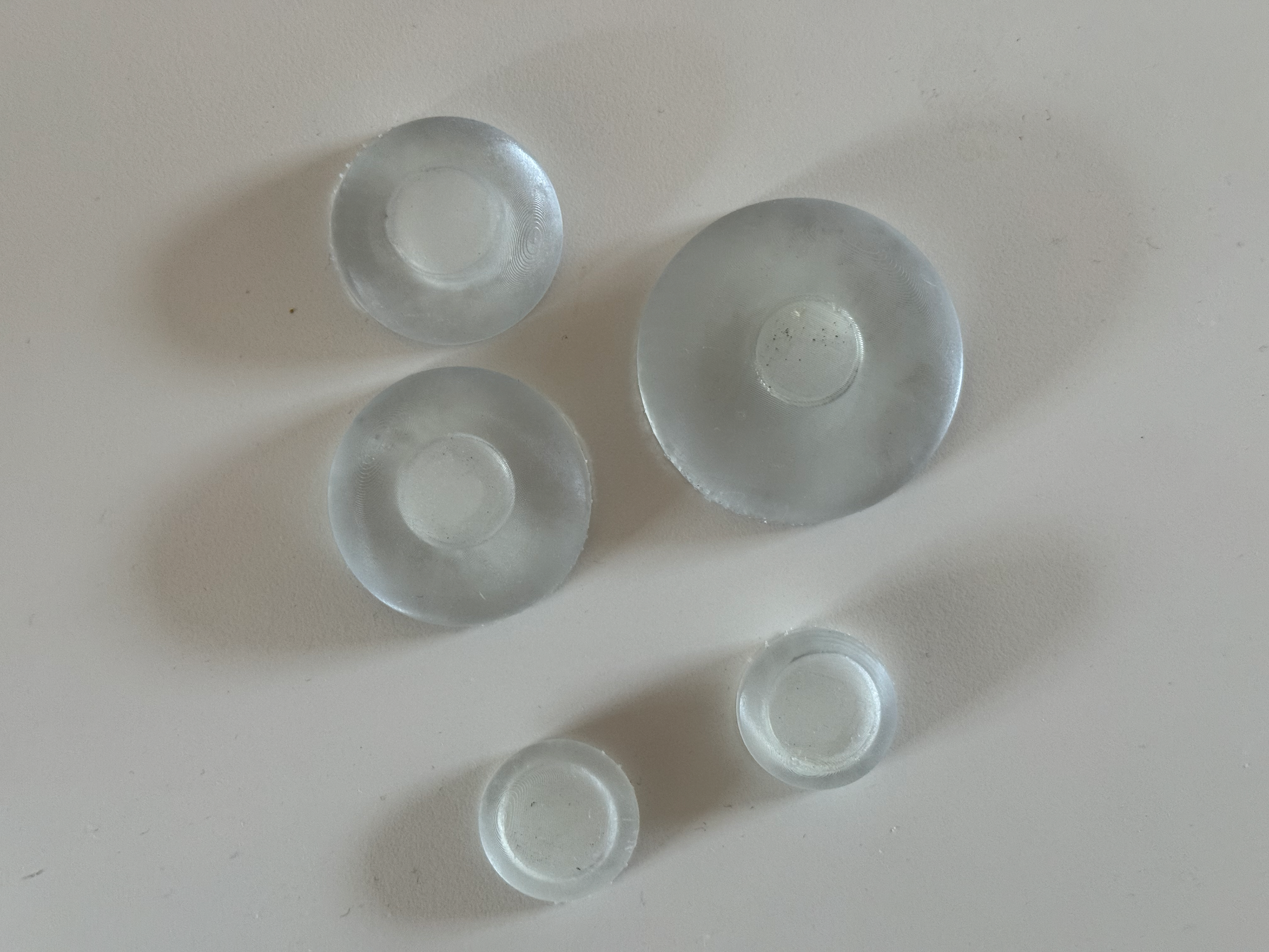
All the lenses including a taller one for Day 351
Inside, turned off. you can see how the objects aren'y perfectly centred around the ring. This is due to the base not being a perfect circle, it follows the heart rate.
Lit up looks interesting but I don't think it works as well as the PETG prints. Maybe frosting the resin would work.
Following the tutorial with Geoff (31/03/2025), I decided to get a resin print of the lenses done. I’m just curious about the result. The first issue was the tolerance; the Bambu Lab A1 is incredibly precise, so with my mounts and the lenses, I don't need to add any tolerance, and they fit together without any issue. However, with the resin, it is much harder, and even after twisting continuously, they still don't loosen. Another issue is that they are so clear that you can see the individual LEDs, which I don't dislike, but it doesn't dispute the light as I wish. This could be solved, but overall it seems like a waste of the time I have remaining. I won't dismiss the idea completely, but for the end of this project, I will.
Sanding
Light off before sanding
Light on before sanding
Light off after sanding
Light on after sanding
From the direct comparison, sanding does not improve the lighting dispersion, but it does hide some of the 3D printing layer lines. While sanding does make it feel nice and up close look nicer, it removes the necessary grip that is needed for screwing. Therefore, I will not sand the lenses as grip is more important than up-close viewing, especially considering the pieces are to be viewed from a distance where the lines can't be seen anyway.
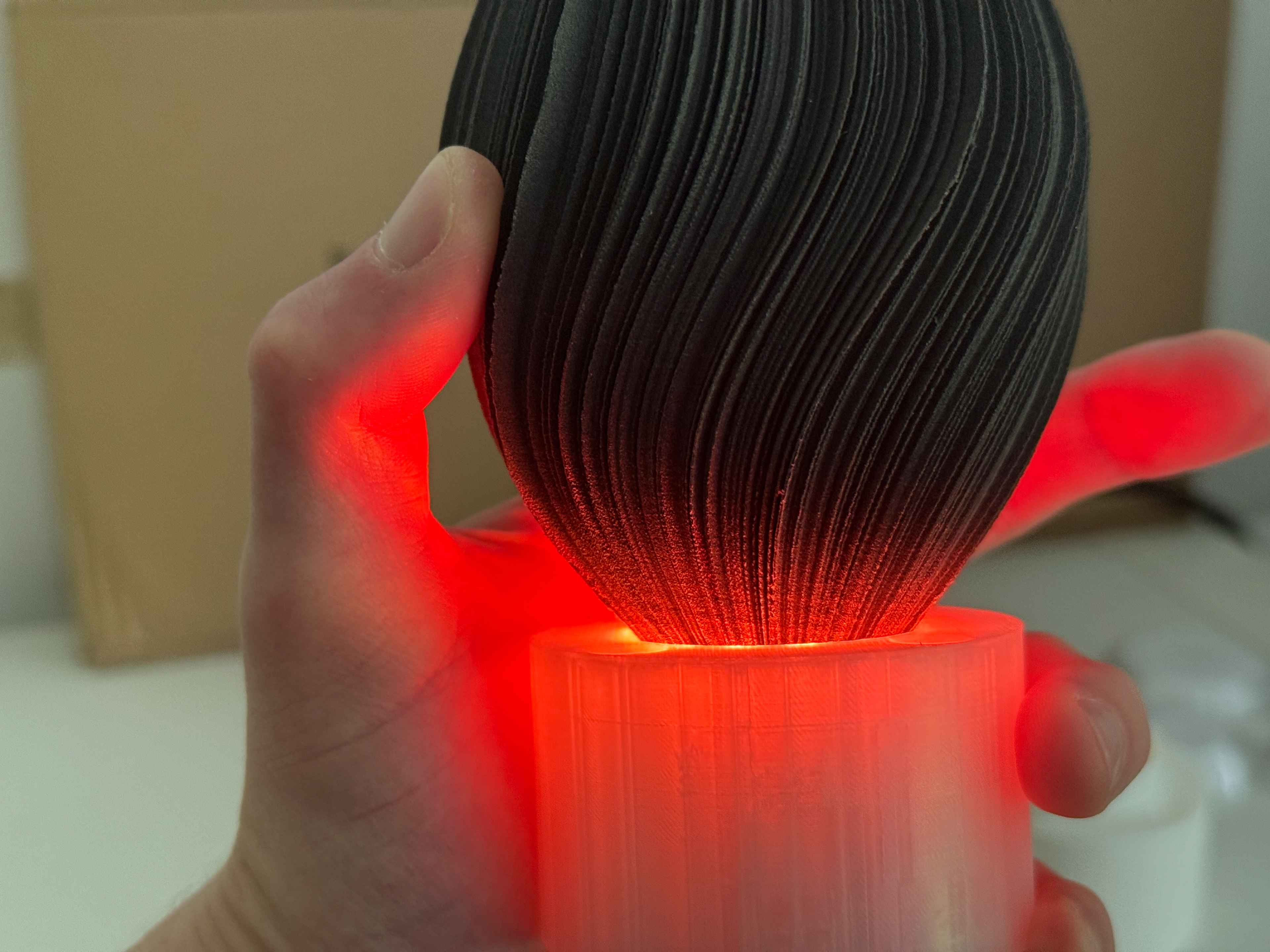
First Look
A first look at the objects. Only one has been wired up. This was to make sure I wasn't missing something completely obvious before I proceed to wire the rest of the objects up. This was at the time I was still waiting for the final print to be done, hence why only three objects are in the photos.
Day 498
Day 498
Day 23
Day 23
Day 351
Day 351
Day 23 lit up
Object Refinement
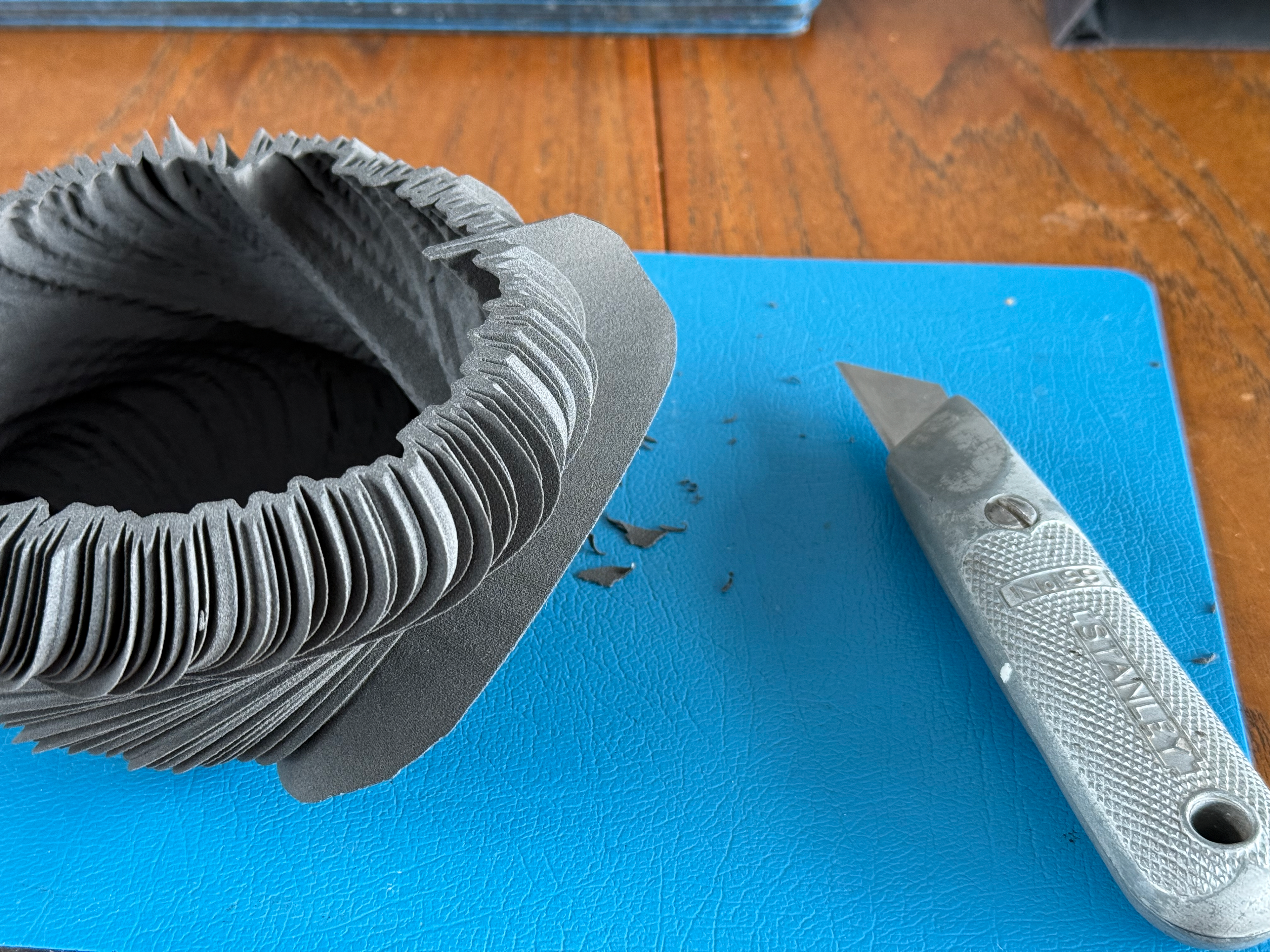
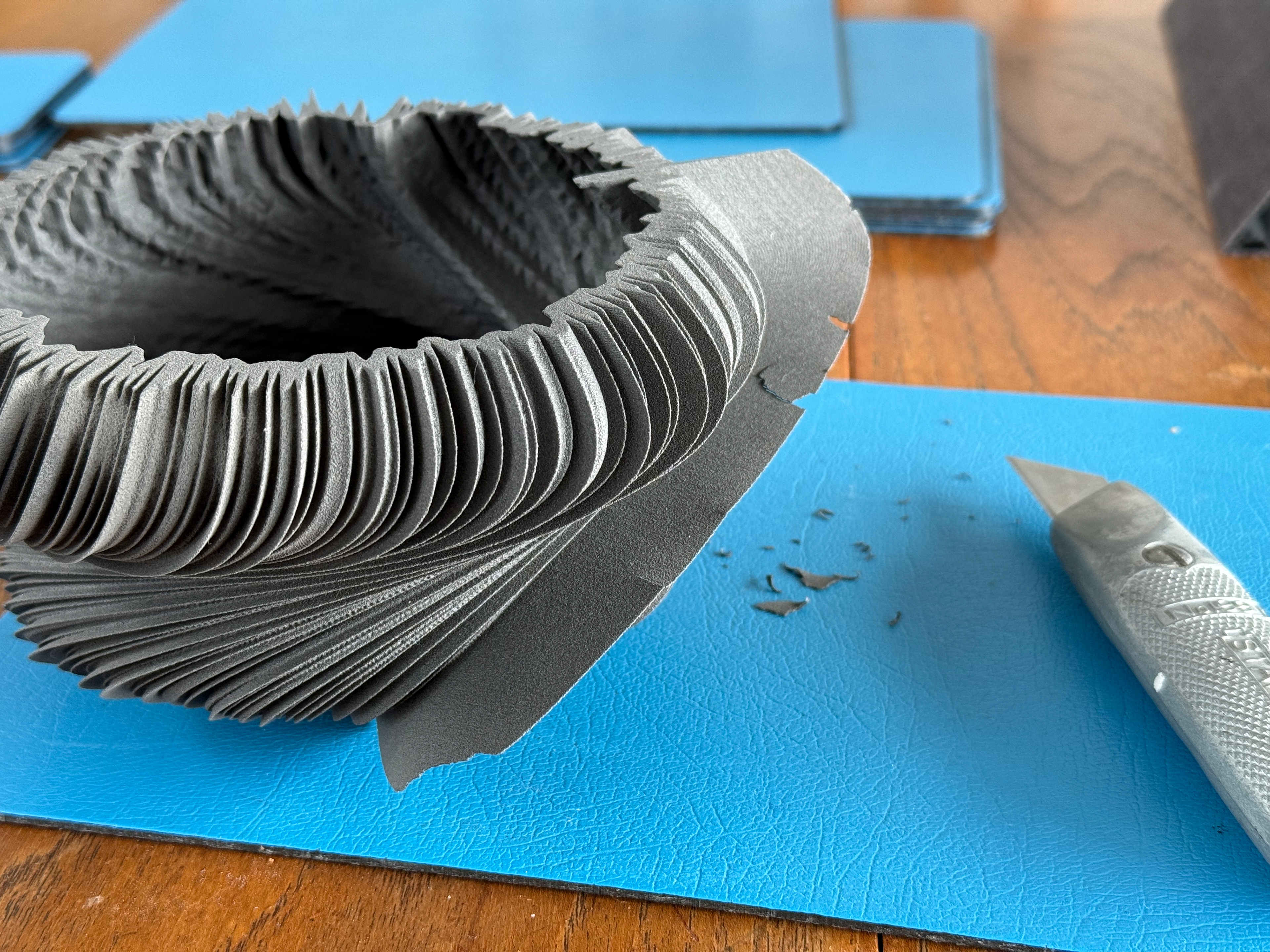
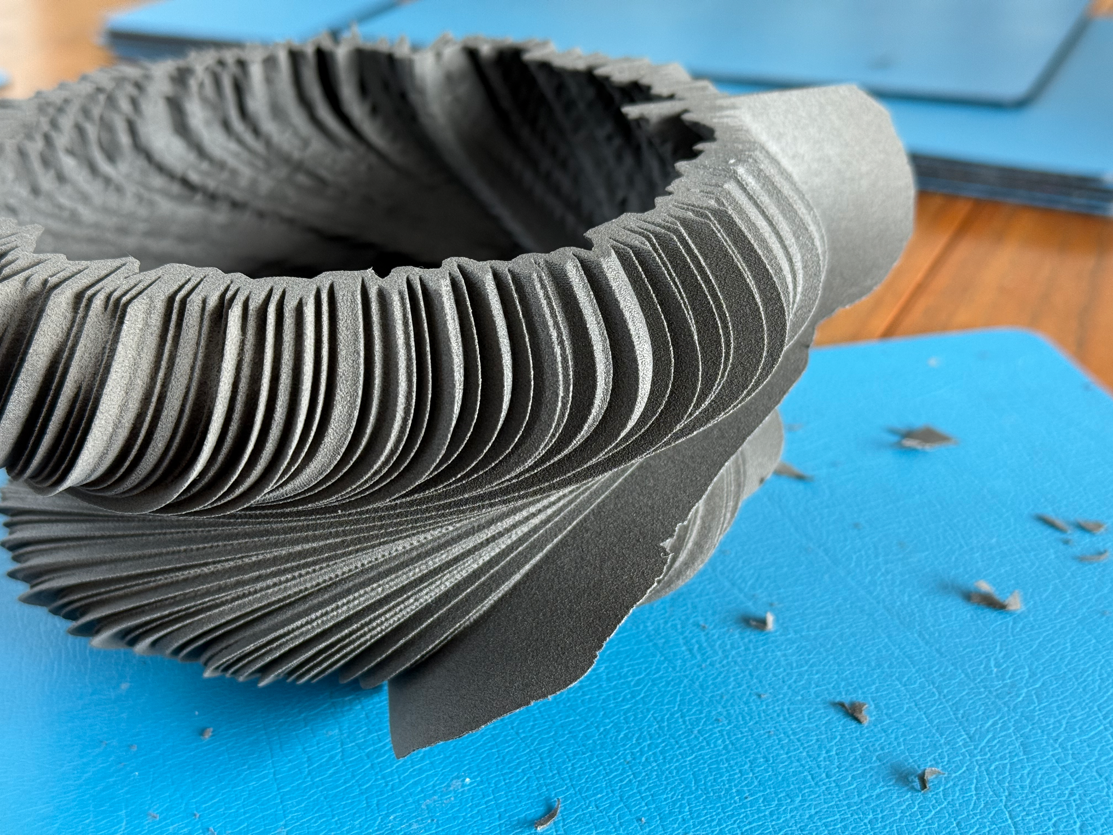
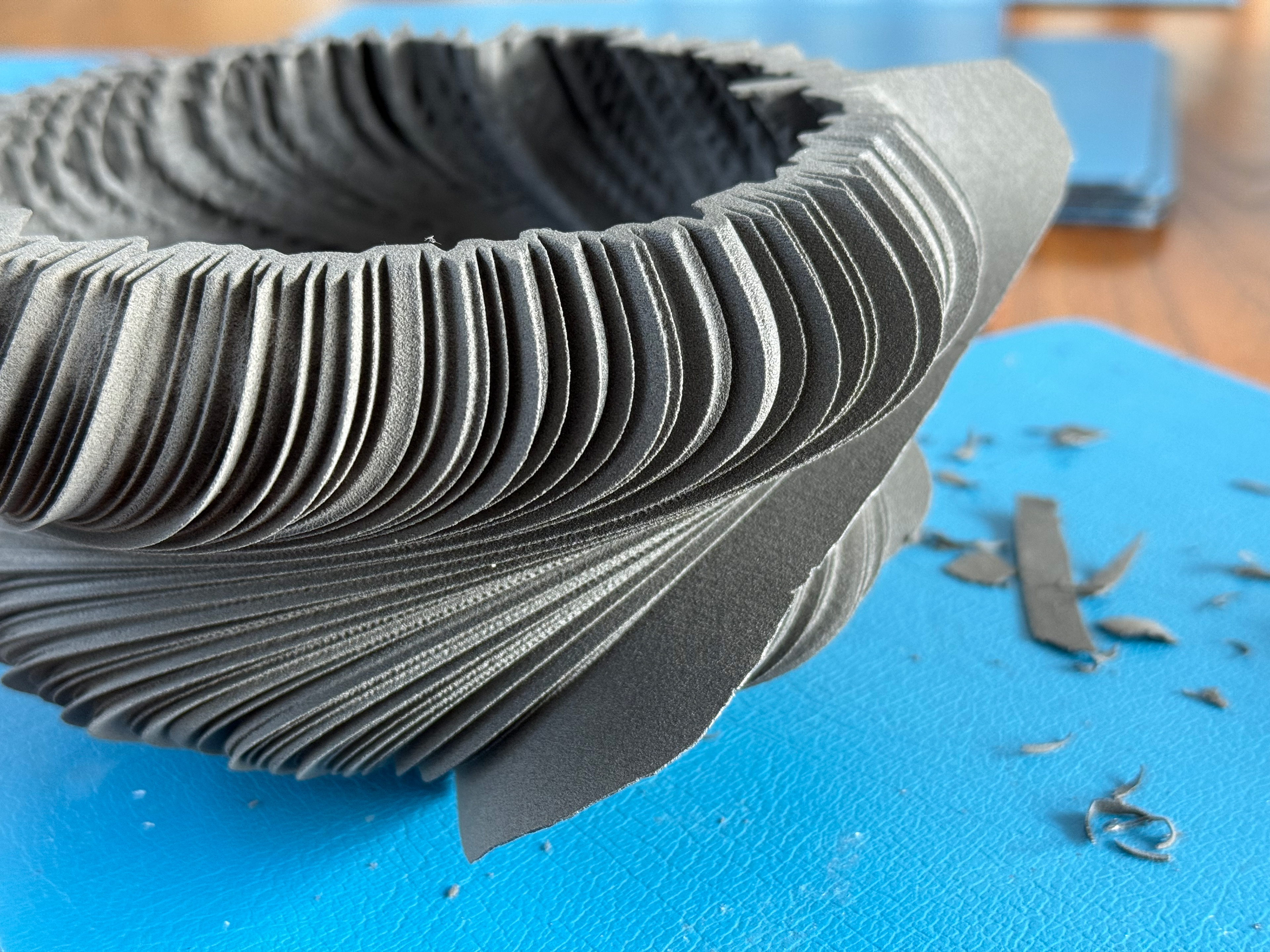
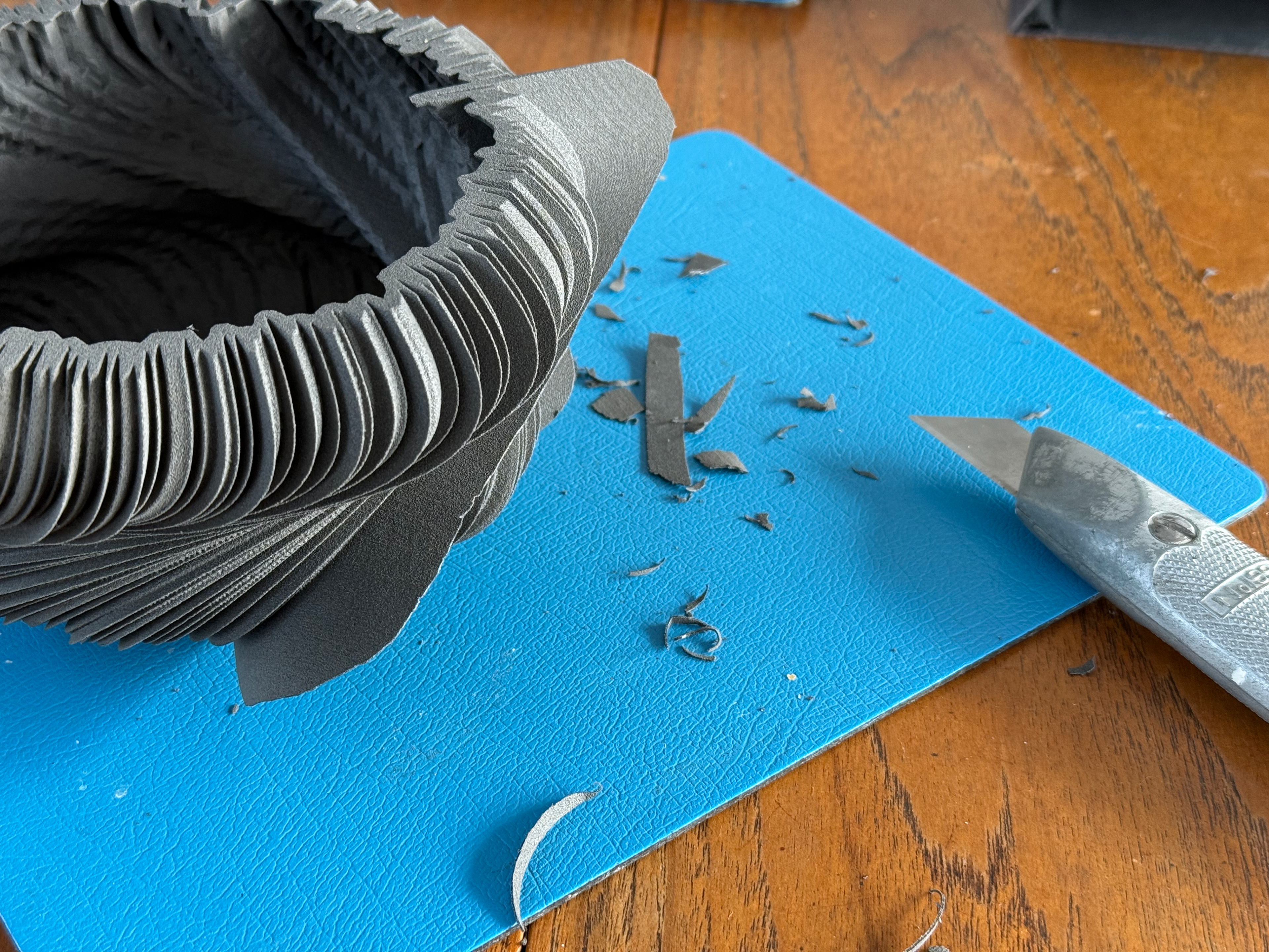
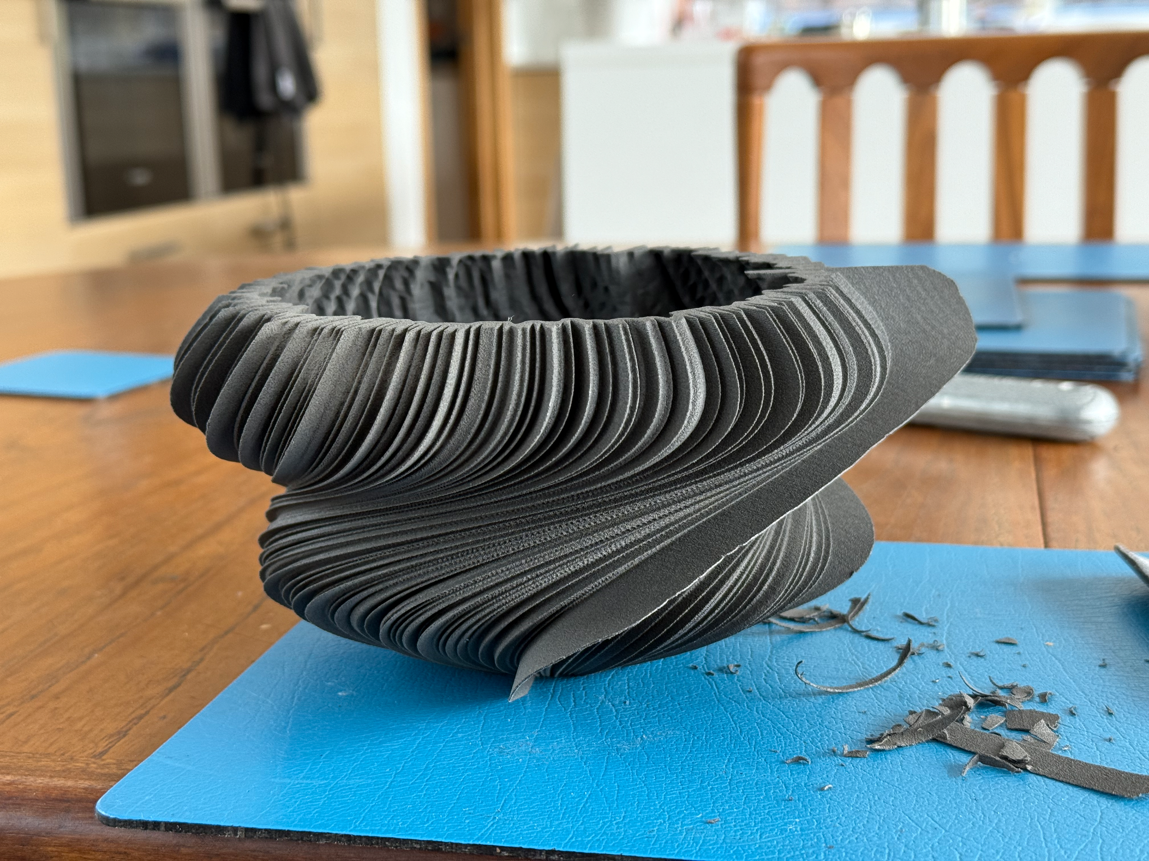
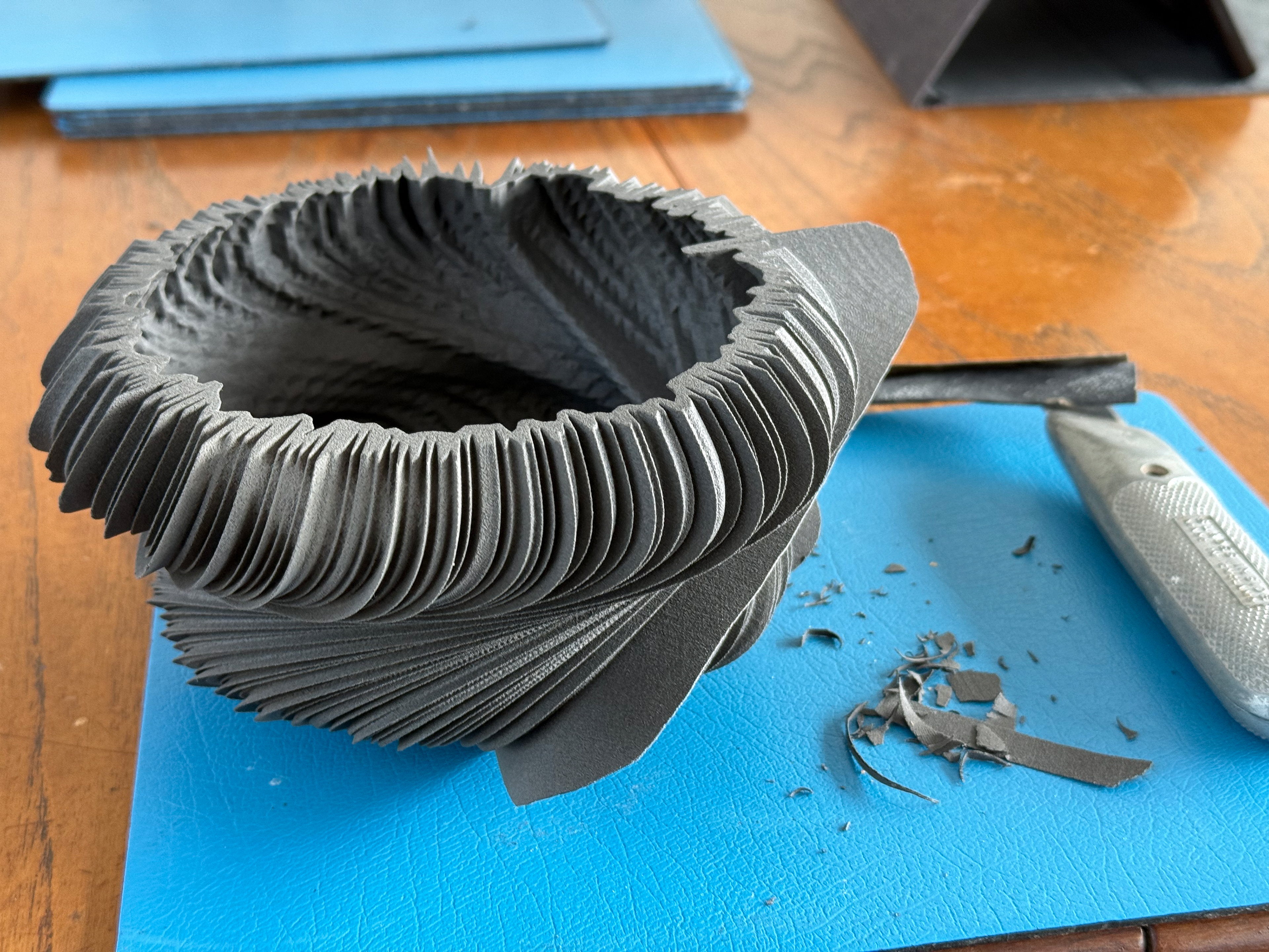
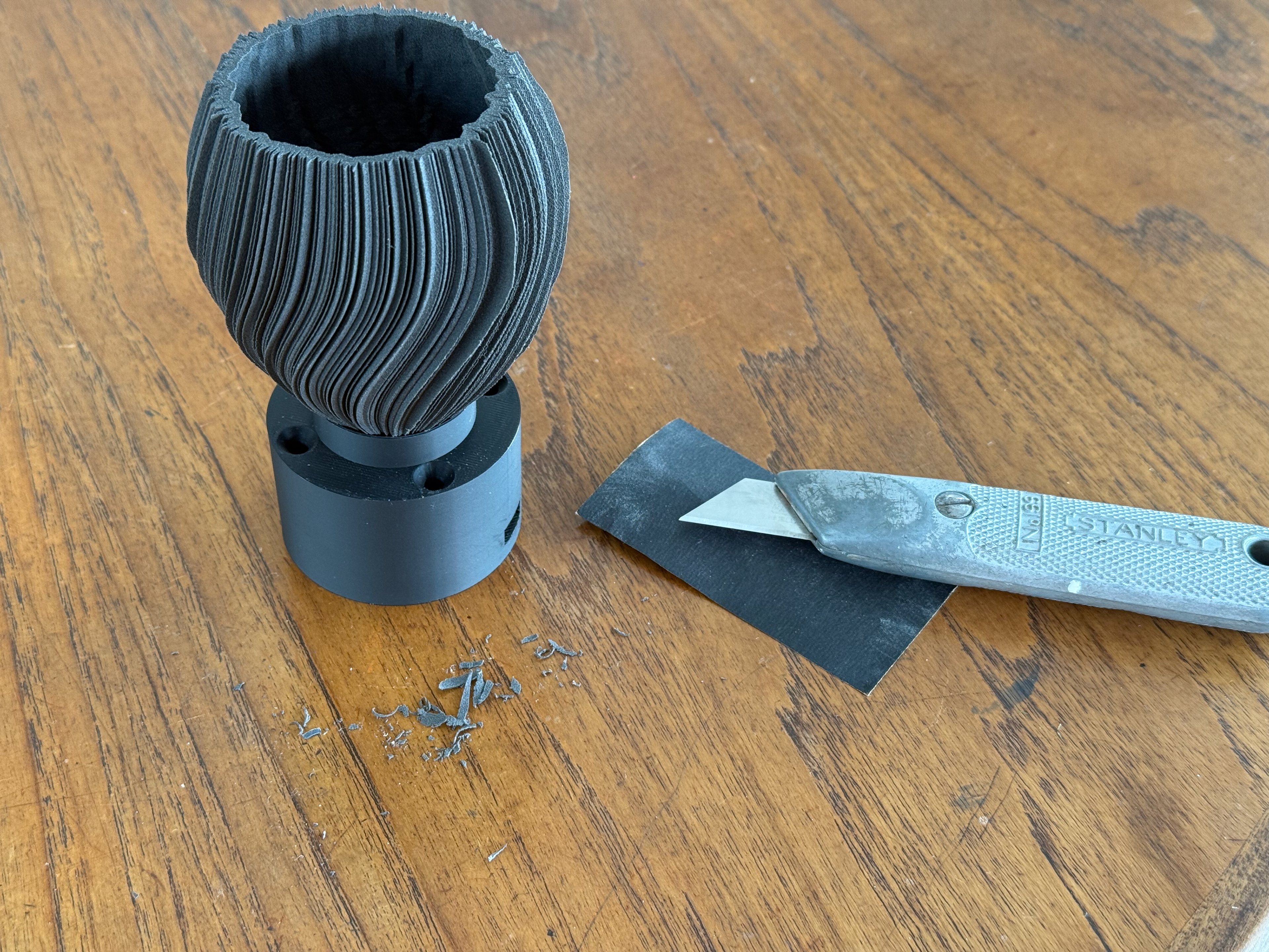
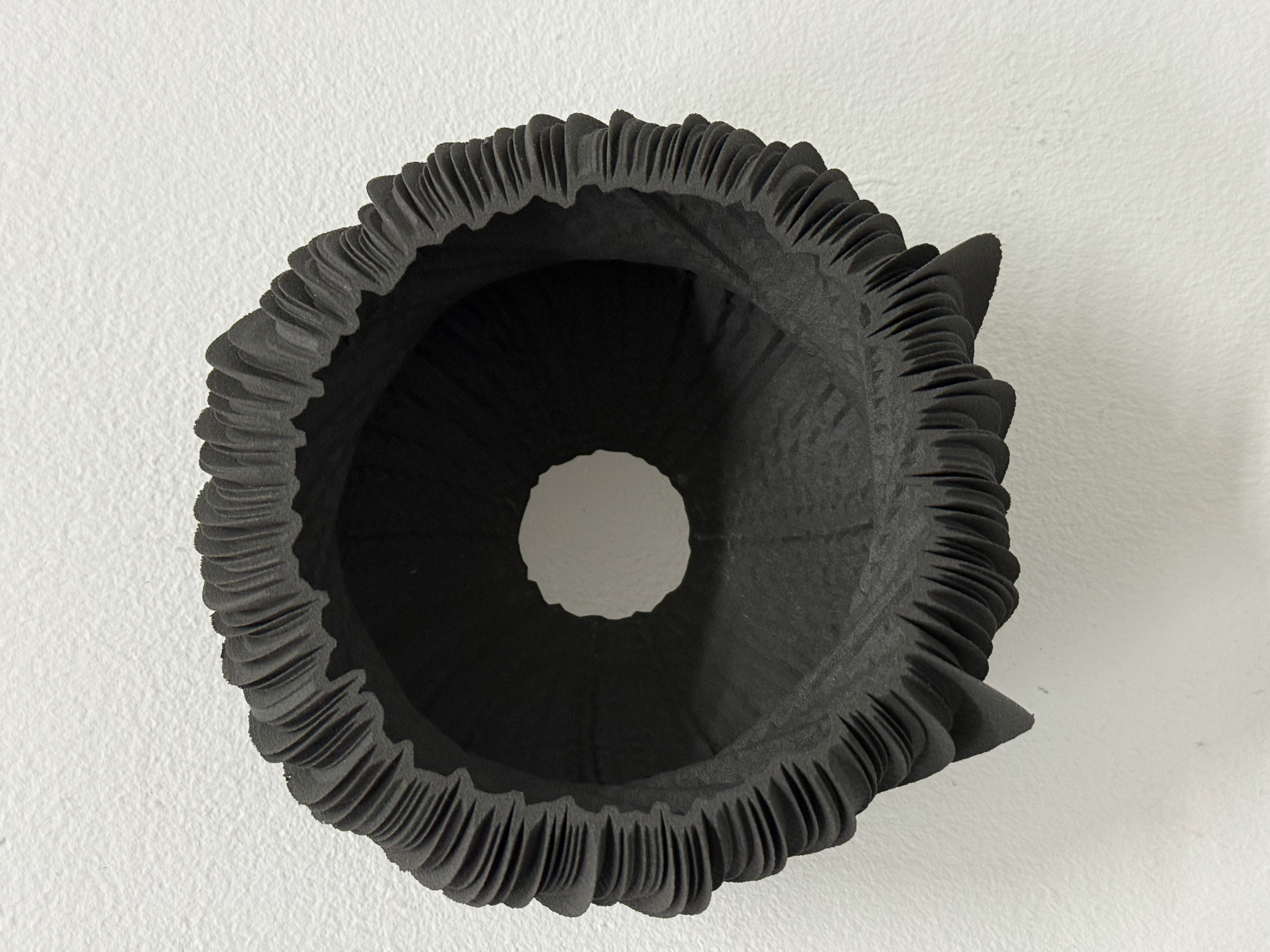
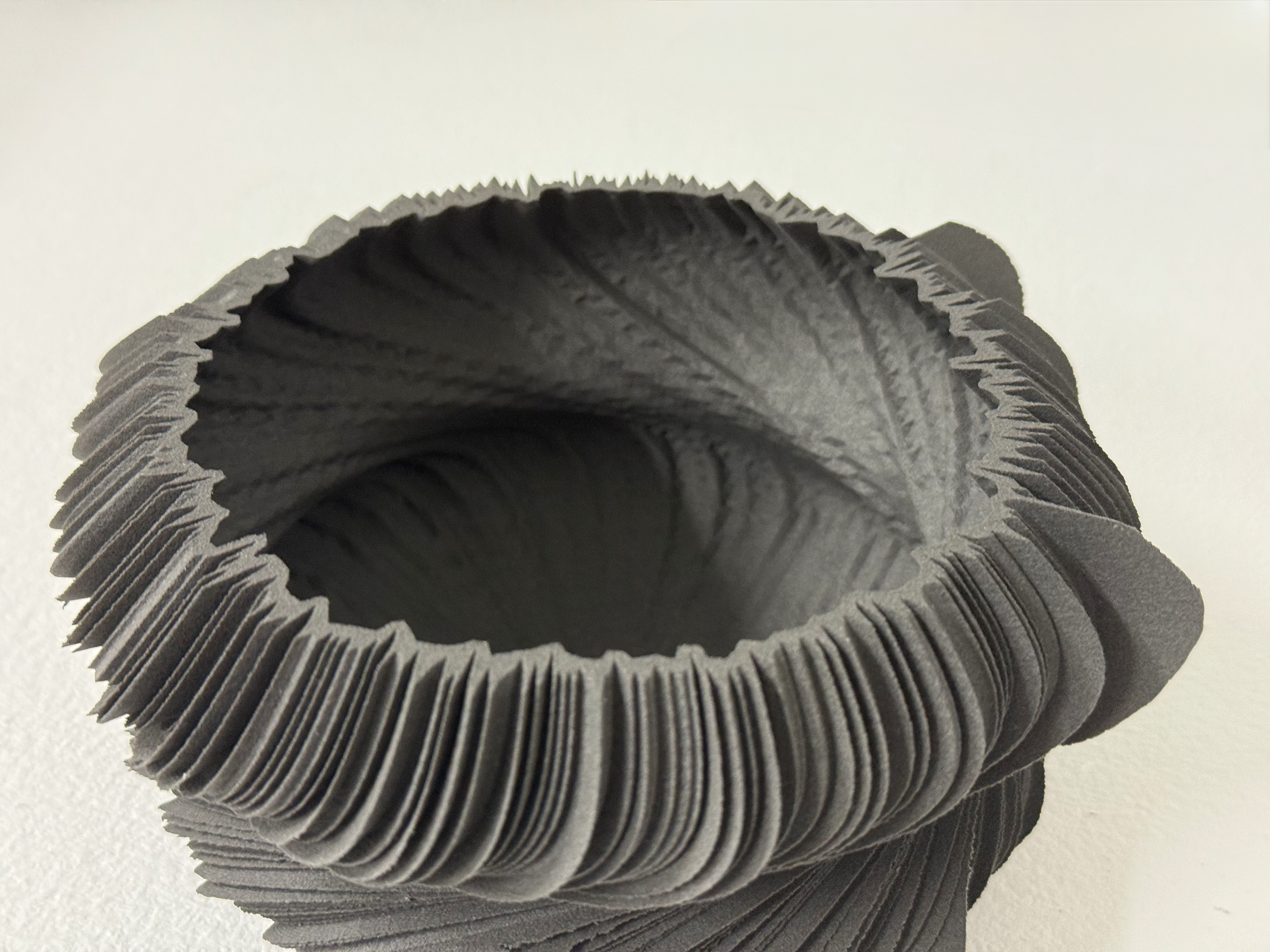
Since the object is 3D printed using SLS, it shouldn't require any further refinement; however, due to the thickness of some of the fins, it doesn't fully print them, or they become damaged at some other stage. So I have to fix them in order to make a presentable-looking object. Personally, I like the idea that the machine wasn't able to print them because it aligns with the incomplete Whoop data as well as the machine’s interpretation of the data— directly linking back to the proposal for the project.
Fixing the fins
The fin to refine
Refined but there is crack you can't clearly see unless you poke it
I poked the areas that had cracked so it's easier to see
Remove of broken section
Continuing refining the fin
The new line
Side profile, you can see the slight wonk in the fin where it's broken
Took out the section that caused it to be wonky
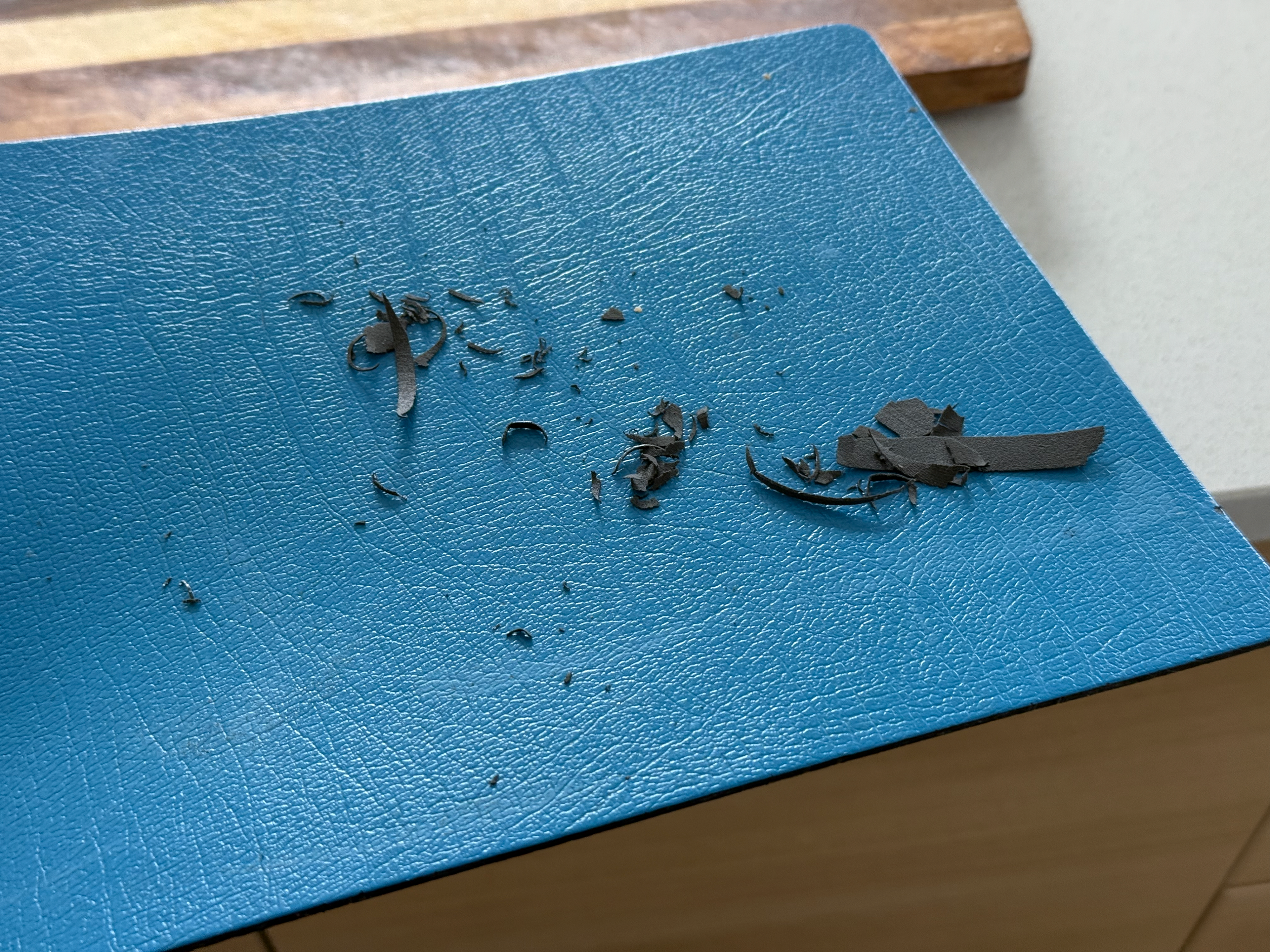
Total amount cut off
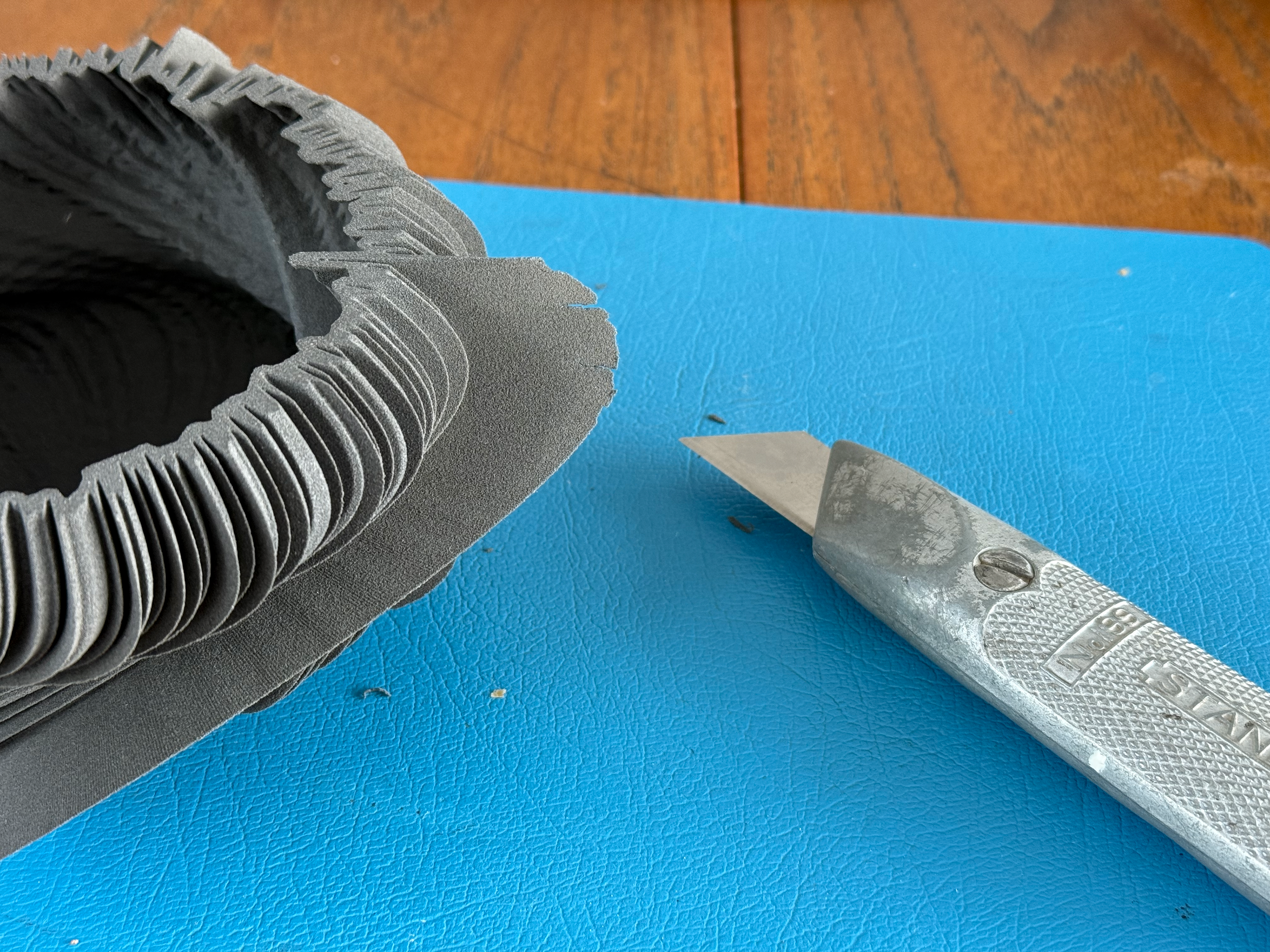
I used a test piece to take photographs of the process as well as to understand how this material reacts to being cut and to sandpaper.
To "fix" the fins, I used a Stanley knife and 600-grit sandpaper. I used a fresh blade to ensure a sharp and accurate cut. I started by tickling the loose edges off, then progressing onto redefining the line to remove any large cracks or sections that are incorrect. Following this, I used sandpaper to remove any final loose edges and to bring back the natural curve.
Day 351 refined
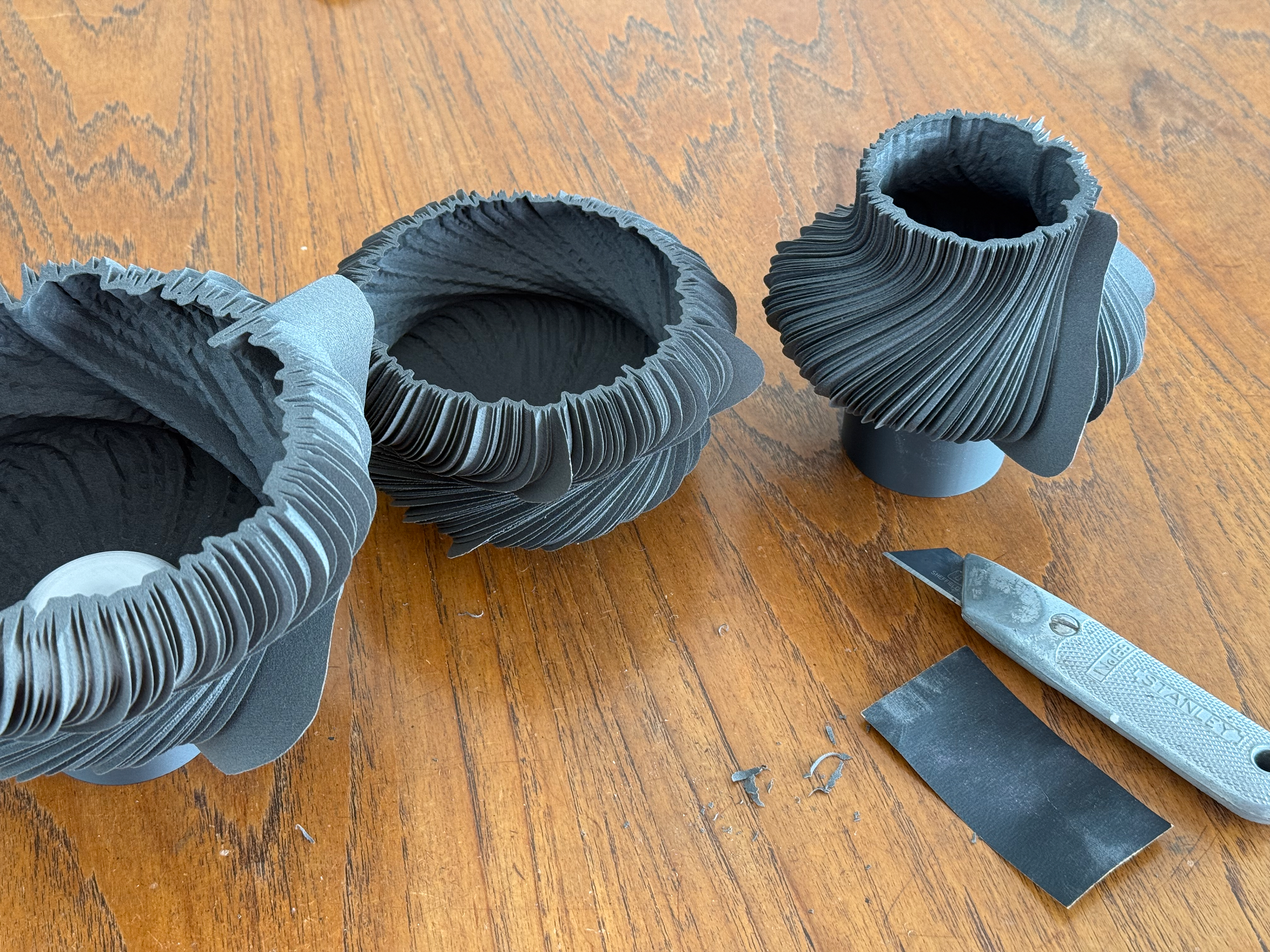
Day 498, Day 72, Day 23 refined
The final amount of nylon was removed from the pieces. The final prints were far more accurate than the test pieces.
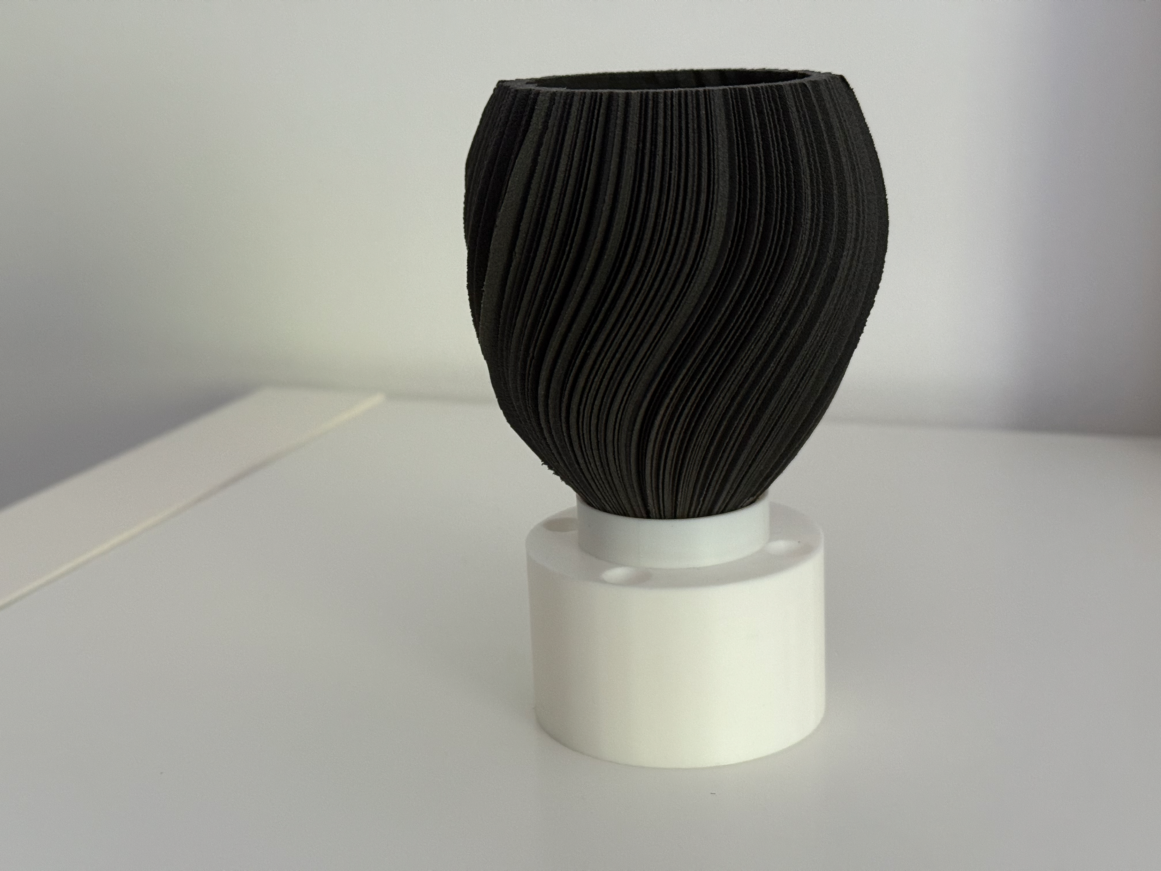
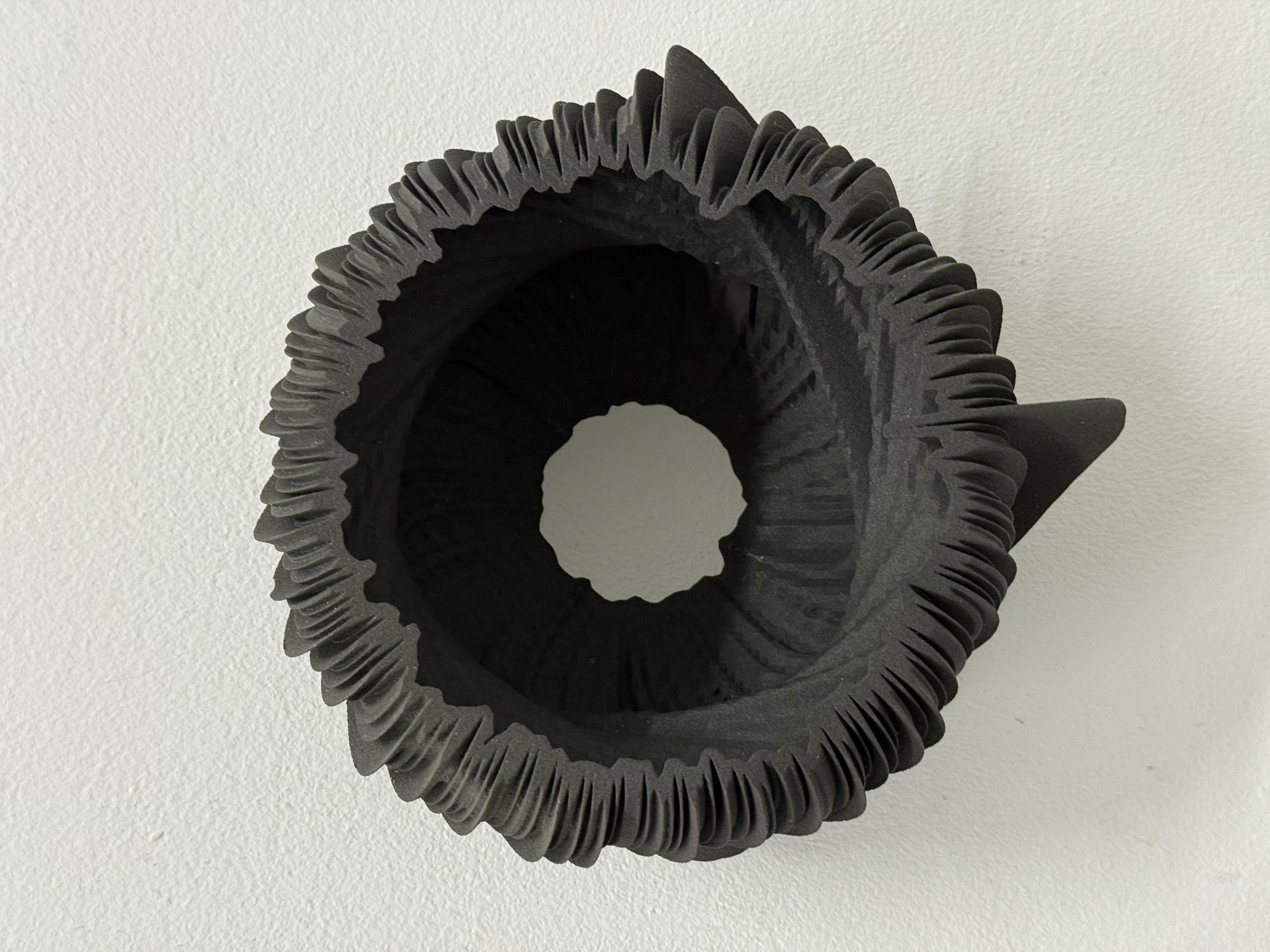
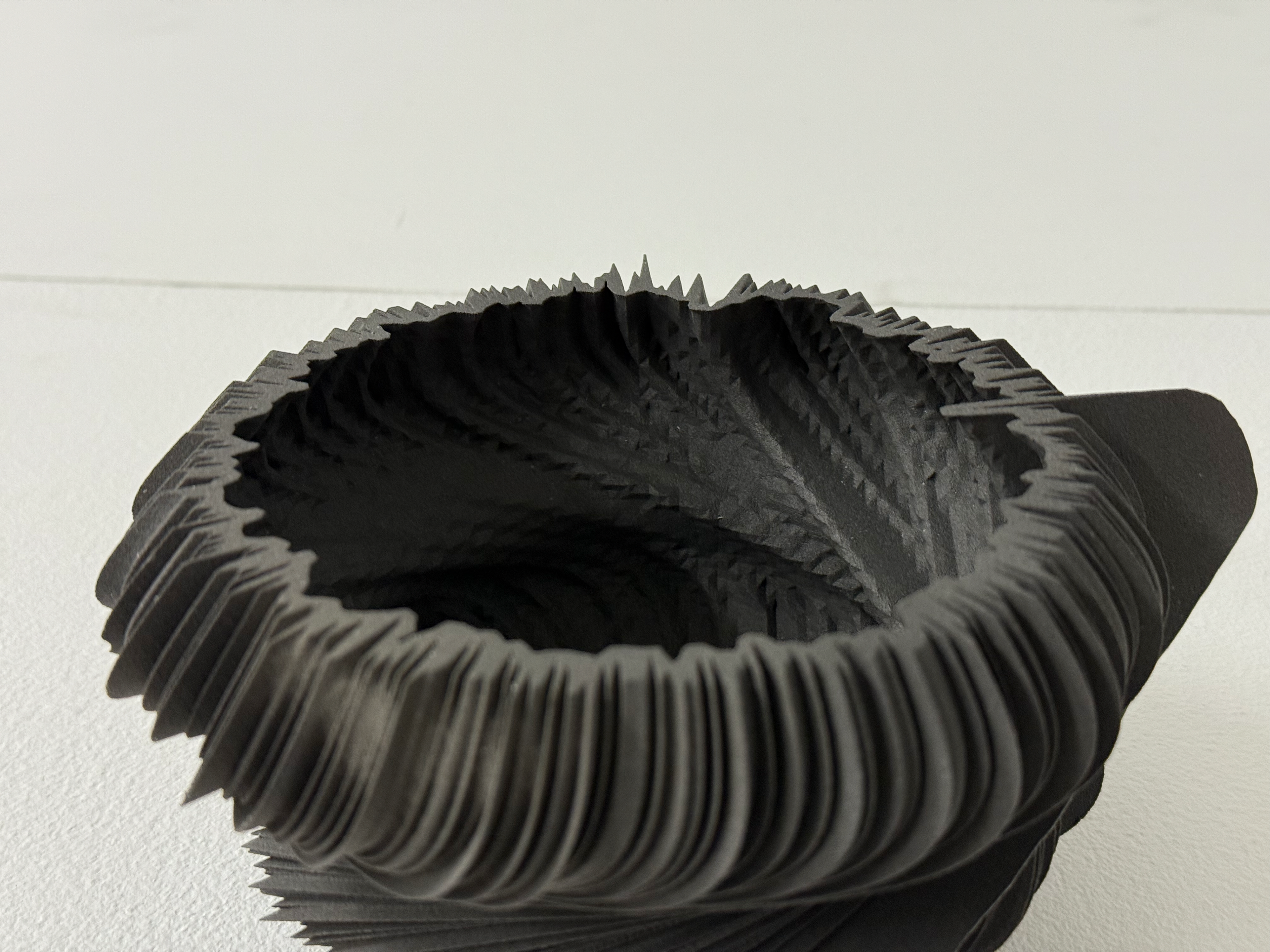
Final Pieces
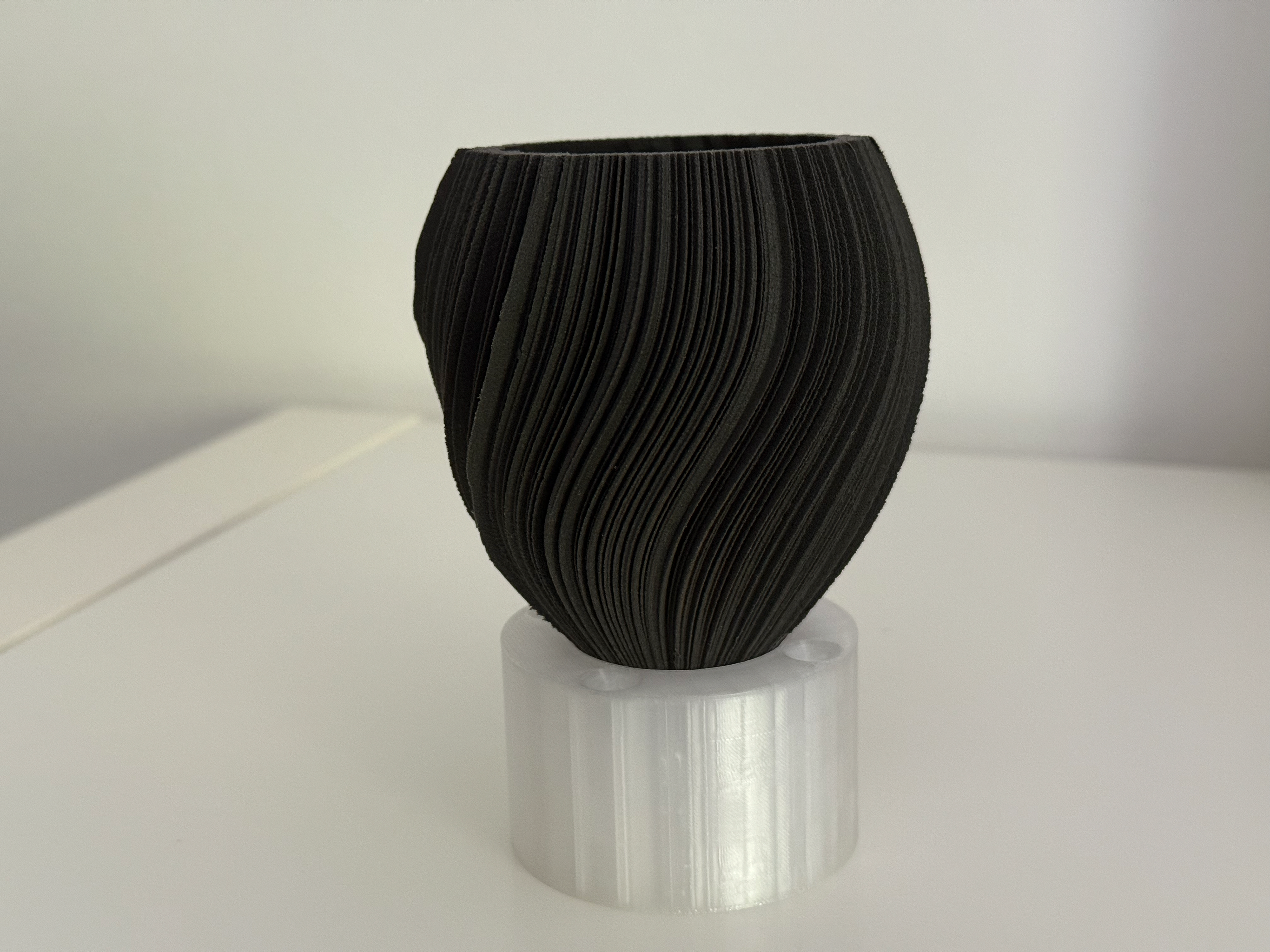
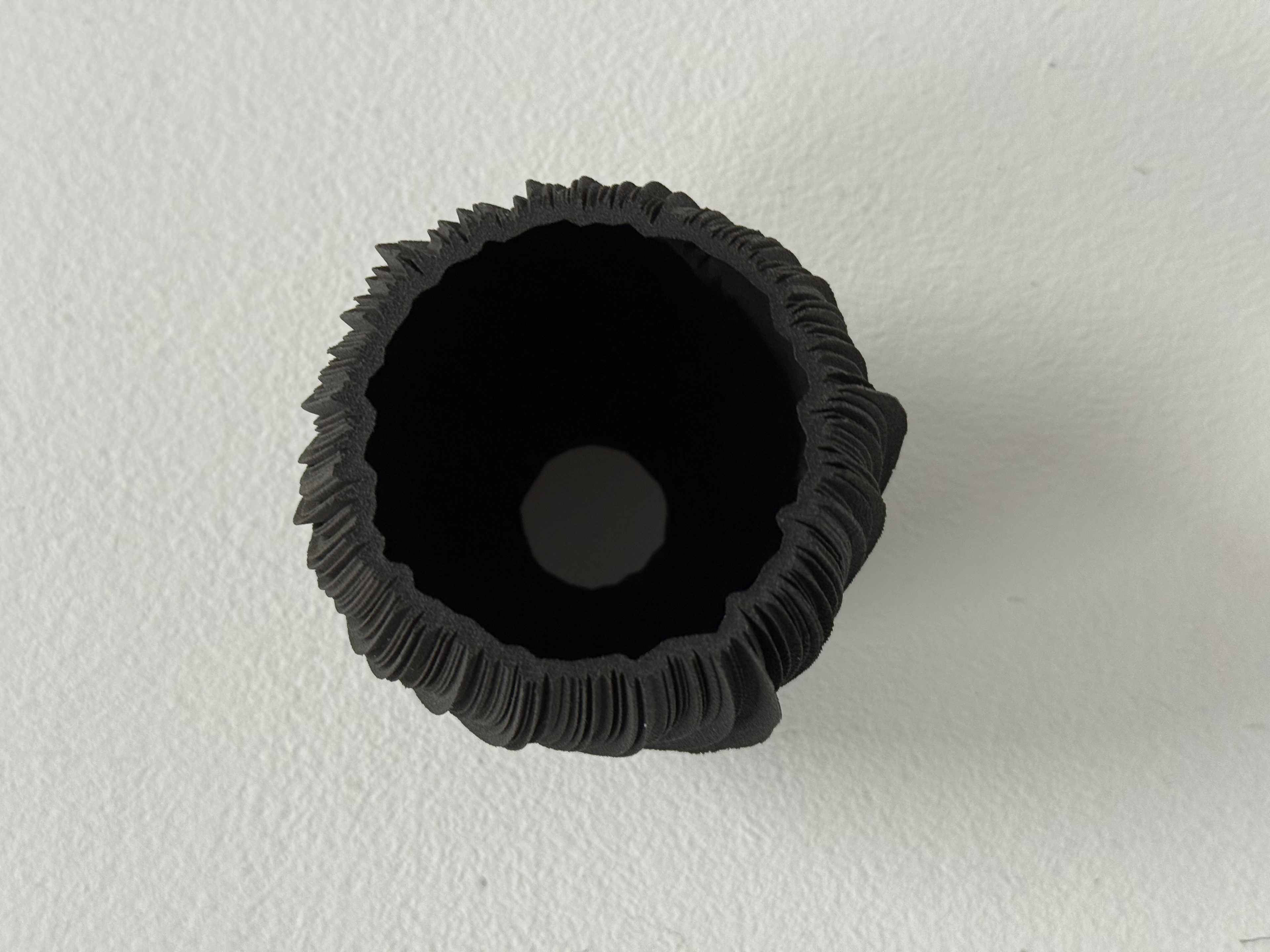
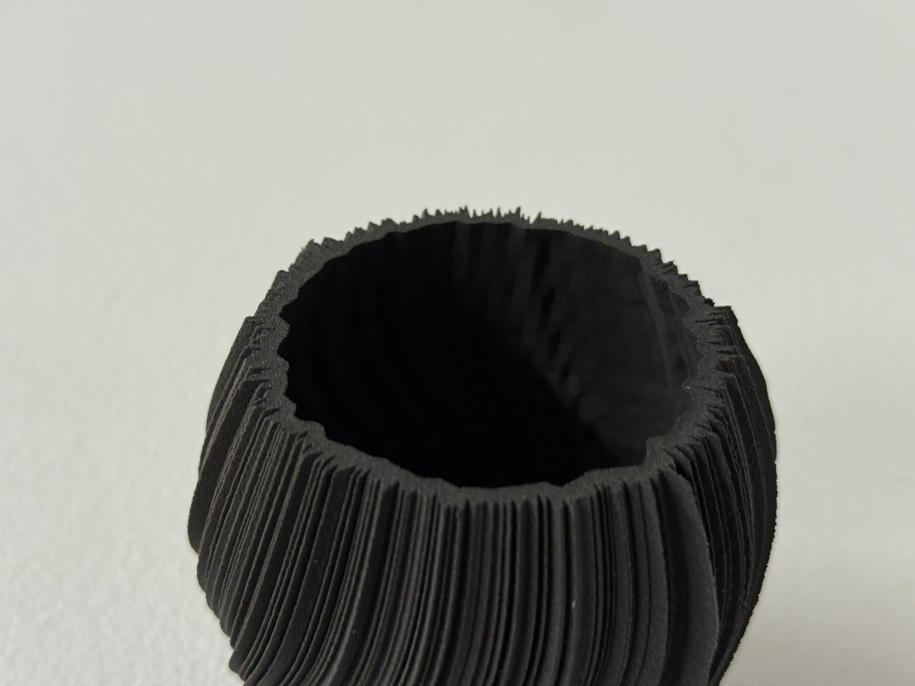
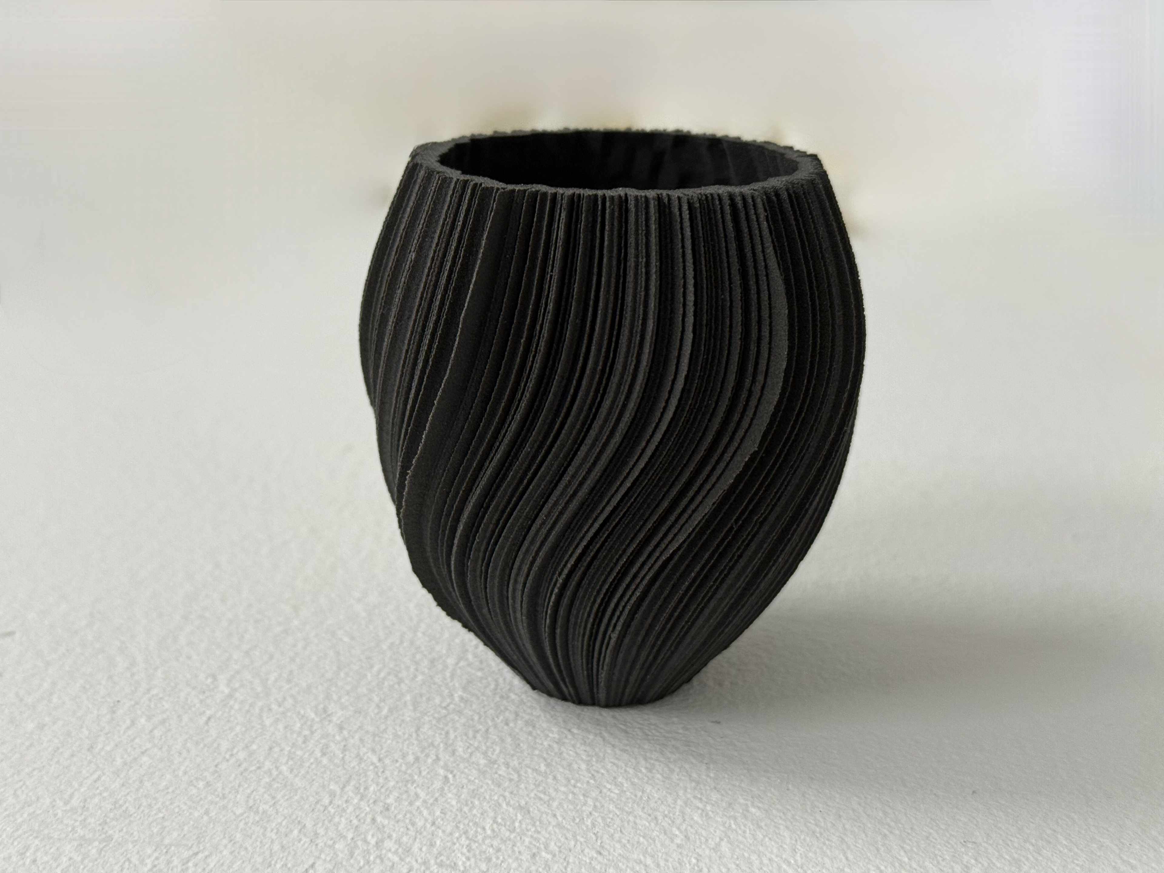
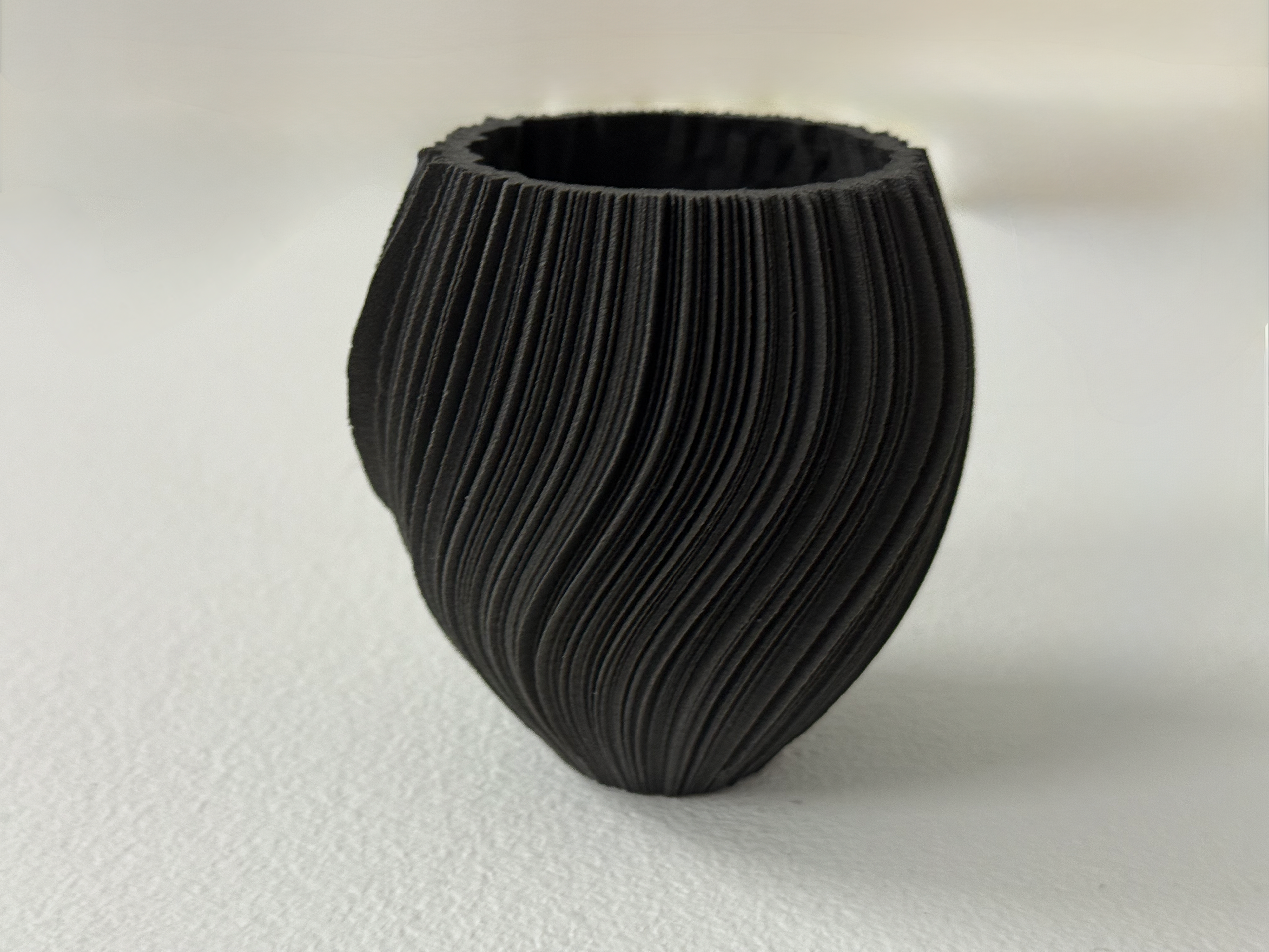
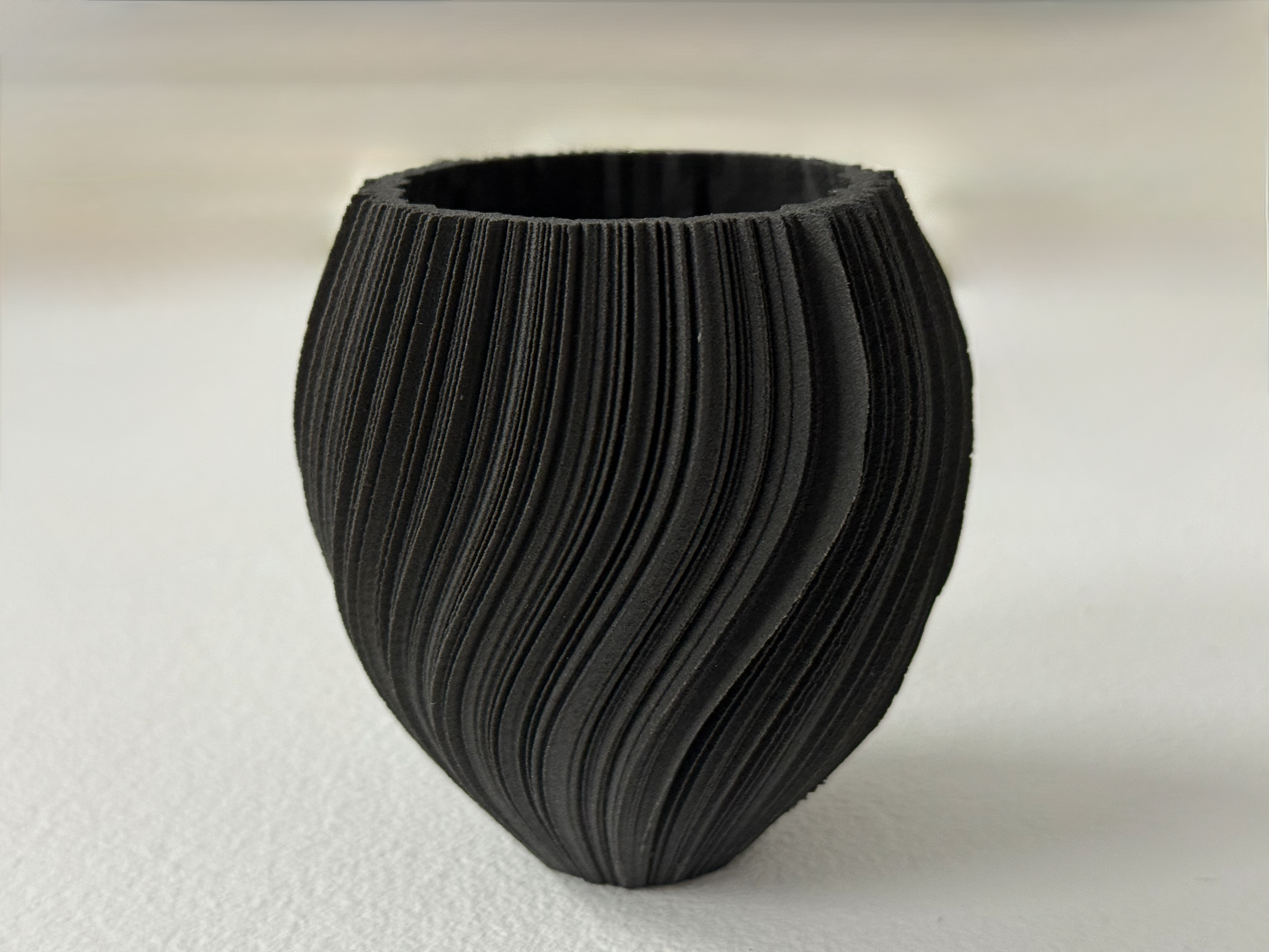
The fully refined nylon prints.
Day 498
My cousin's best night’s sleep.
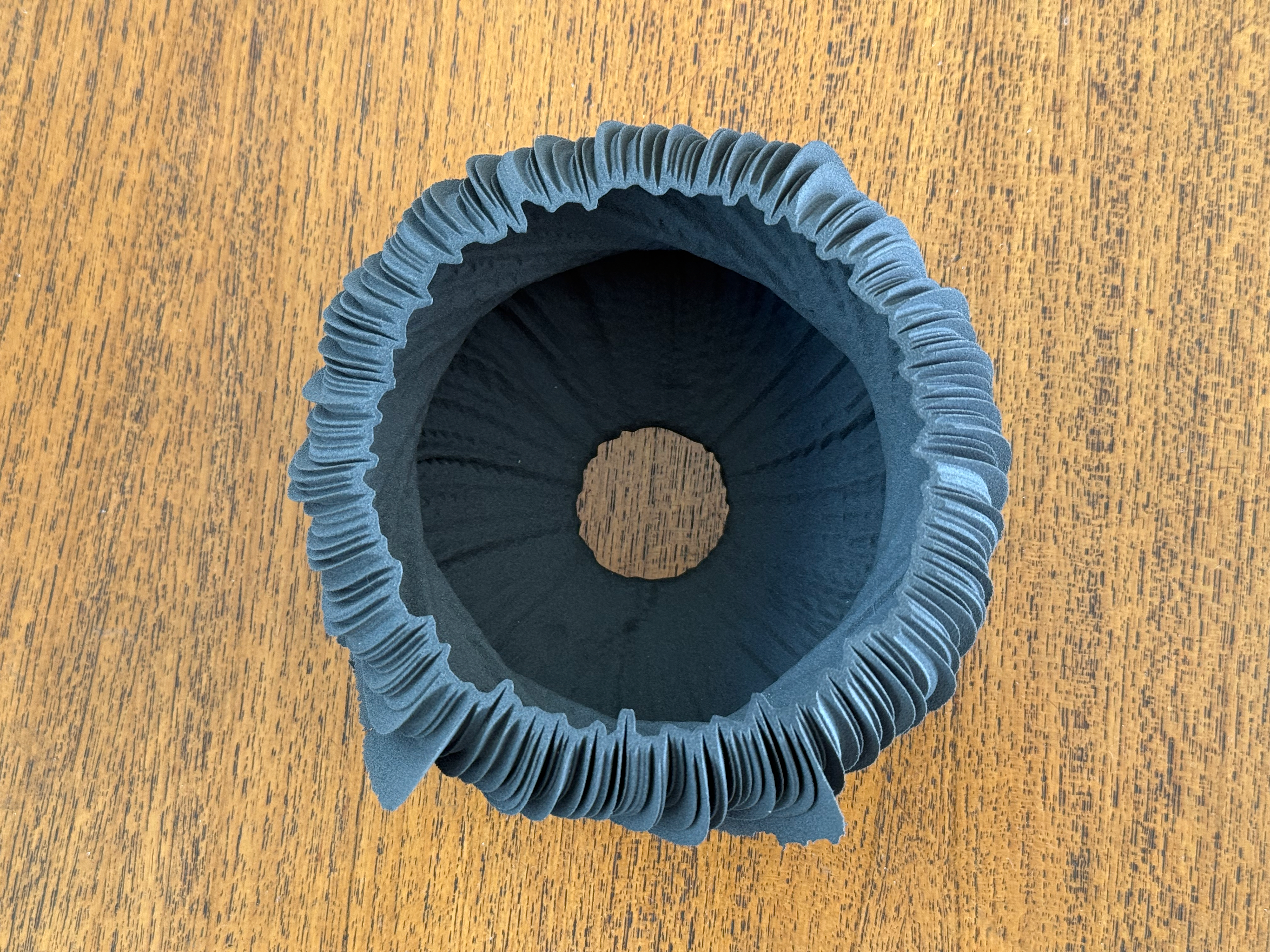
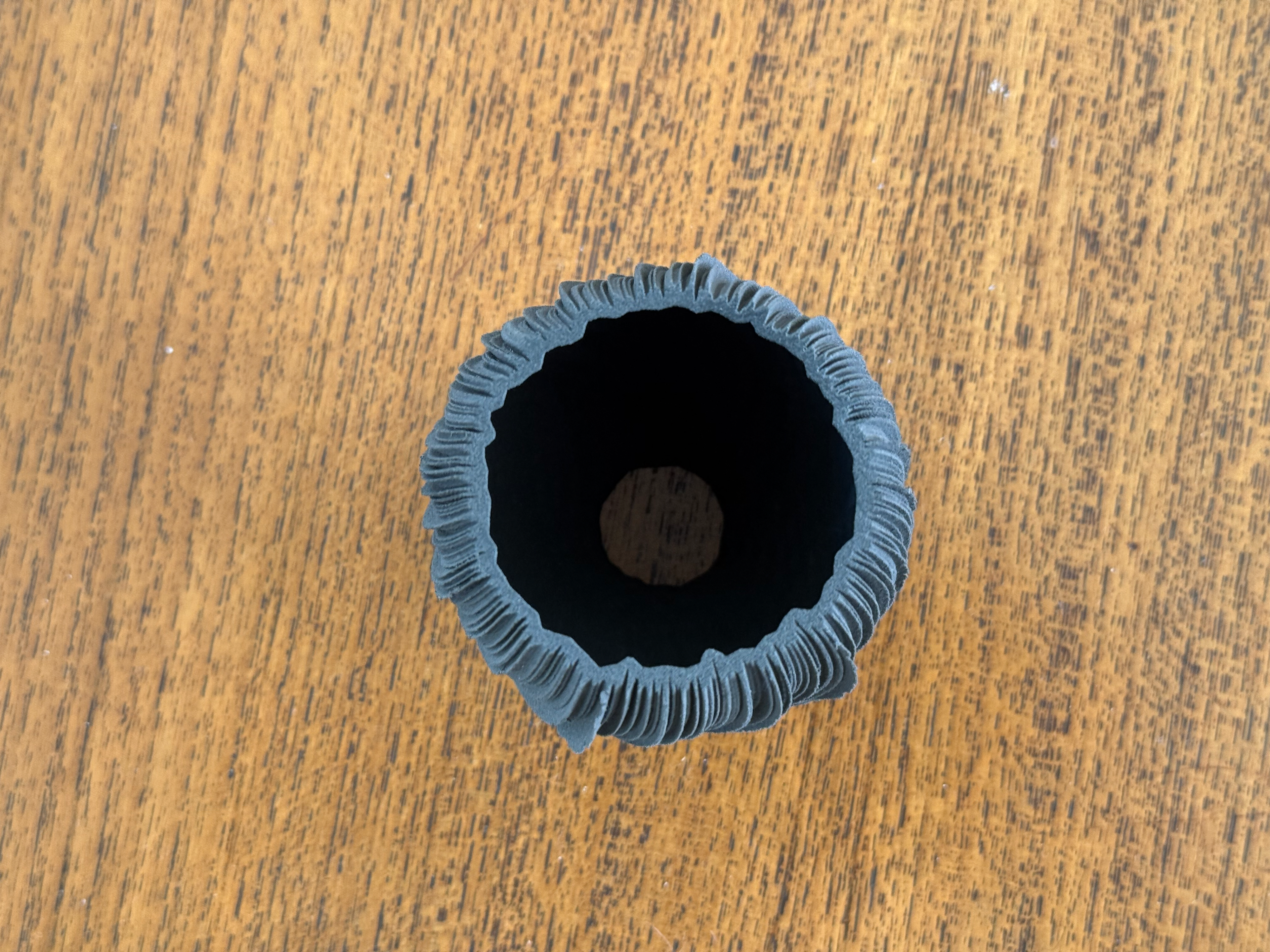
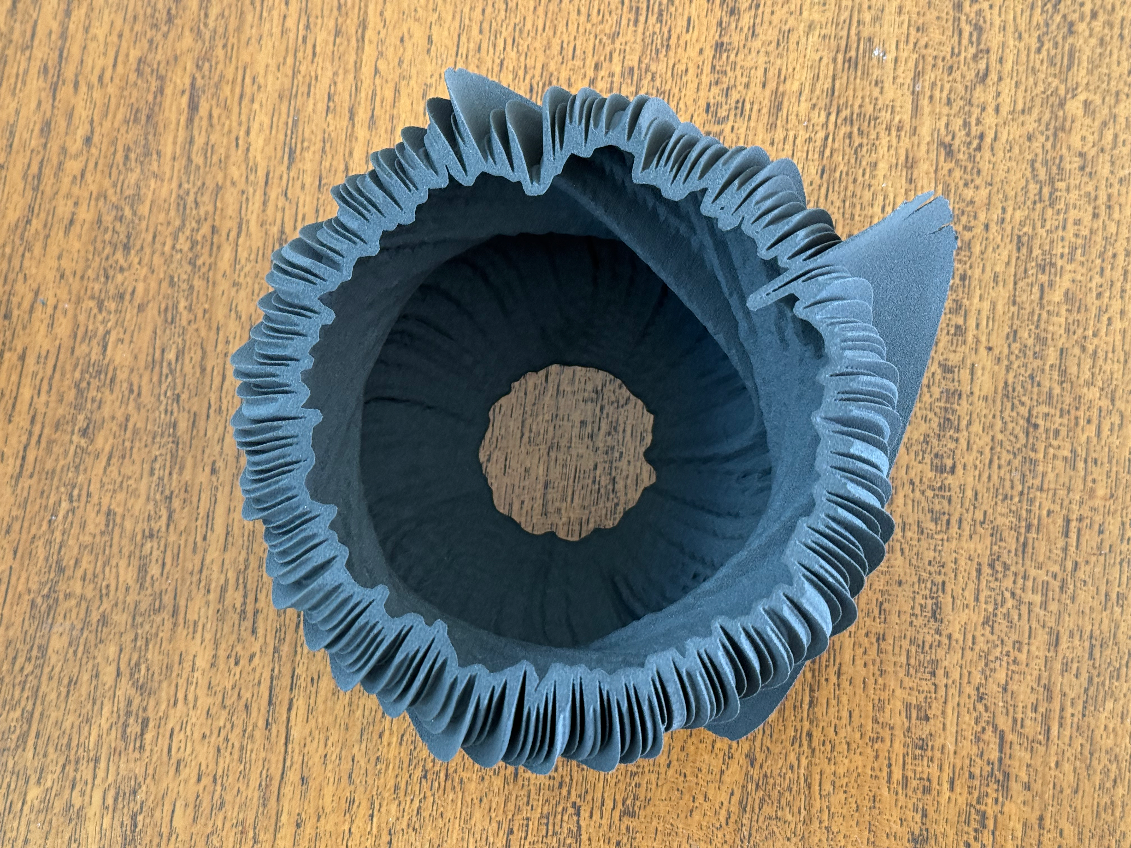
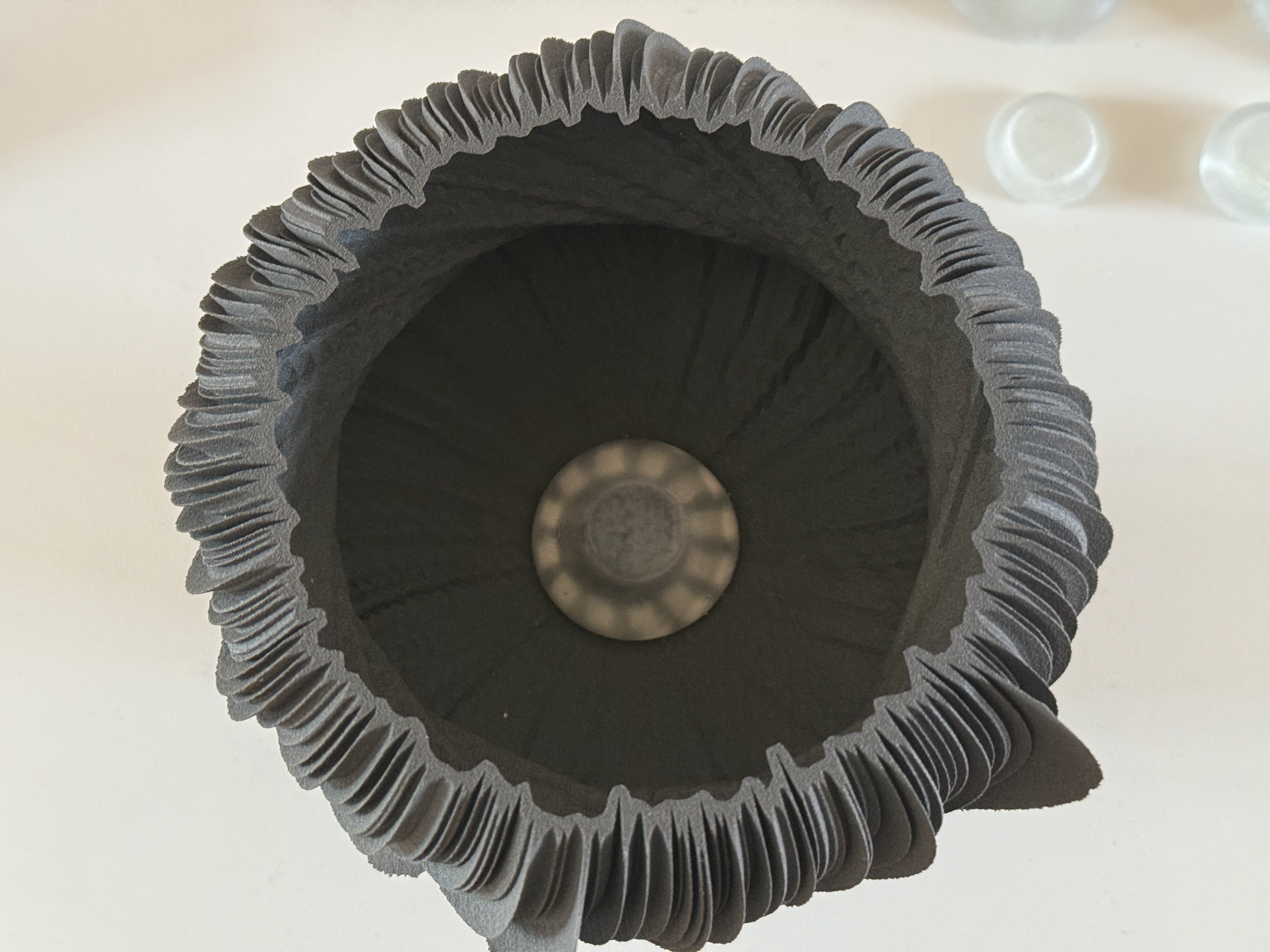
Top view
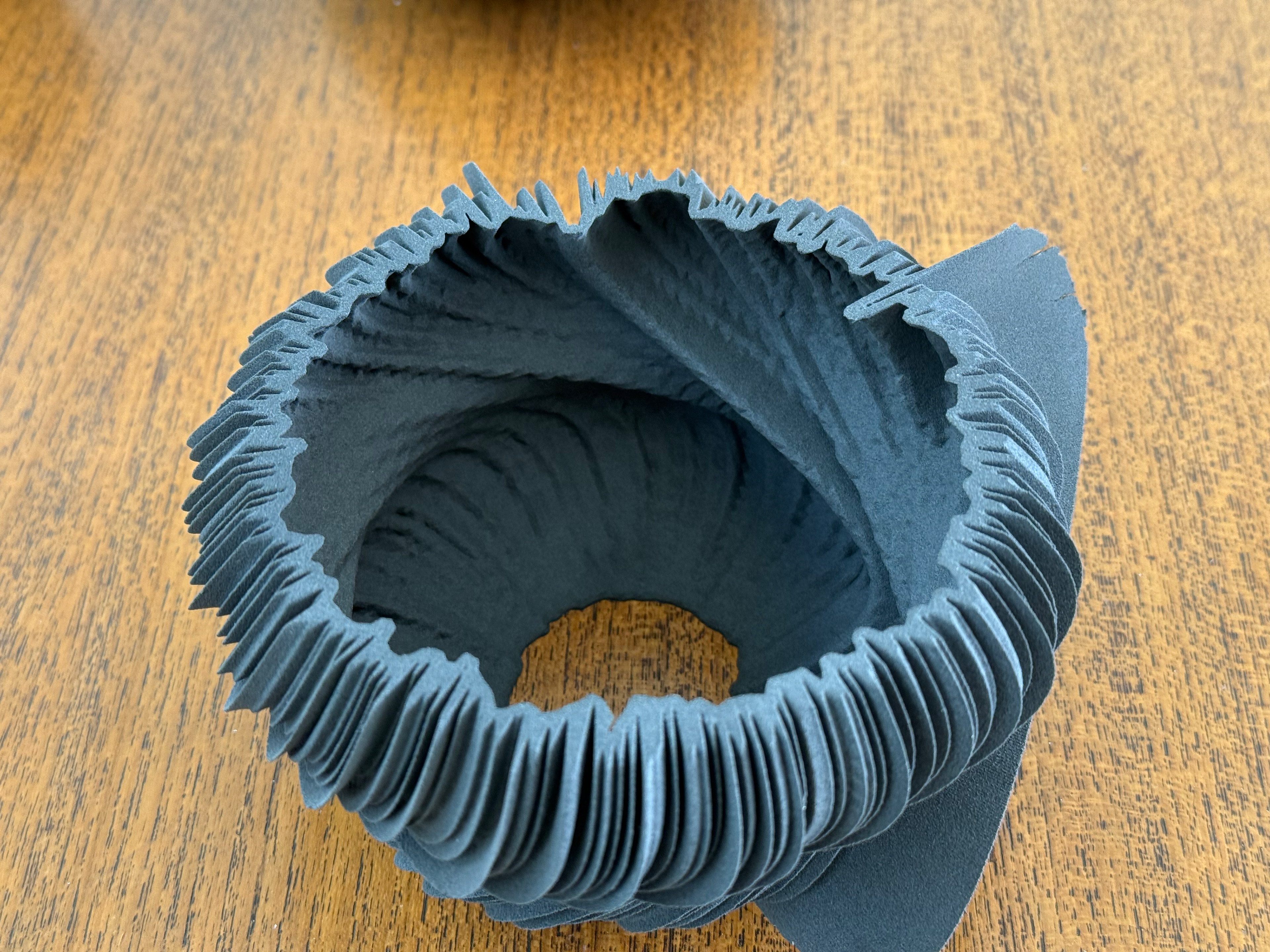
View into the inside
Side view
Side view
Side view
Side view
Day 23
My cousin's worst night’s sleep.
Top view
View into the inside
Side view
Side view
Side view
Side view
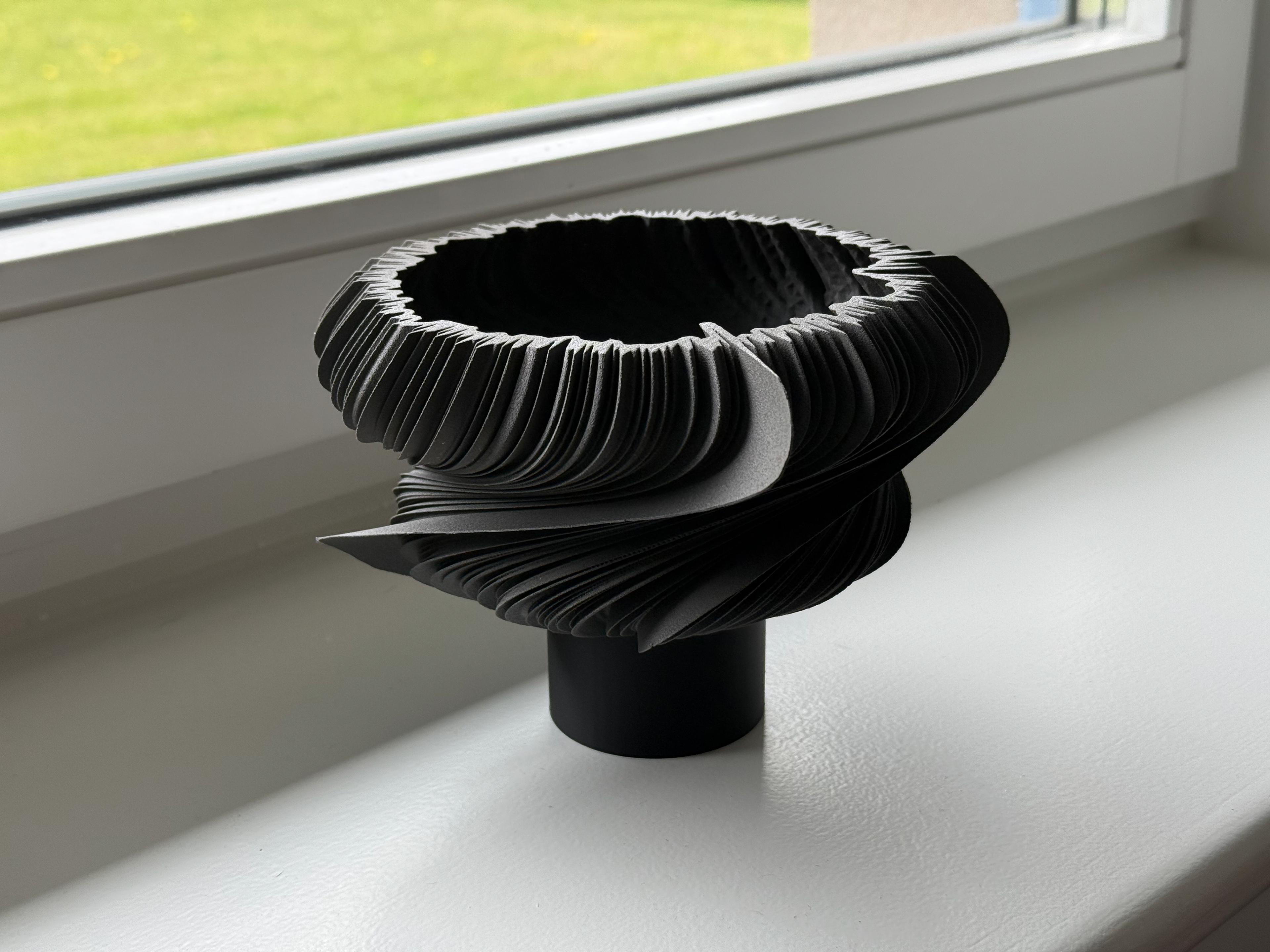
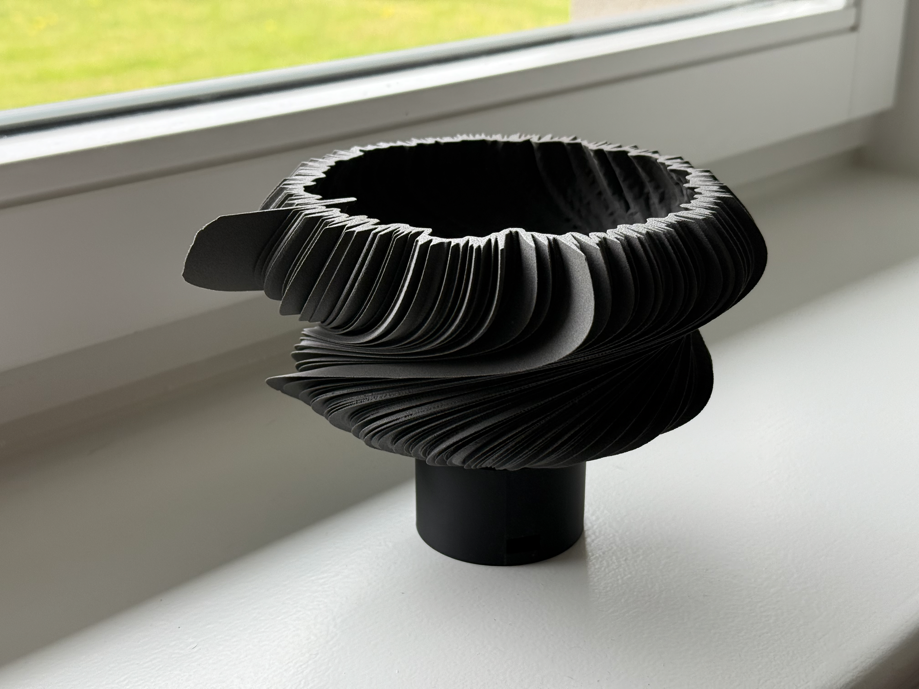
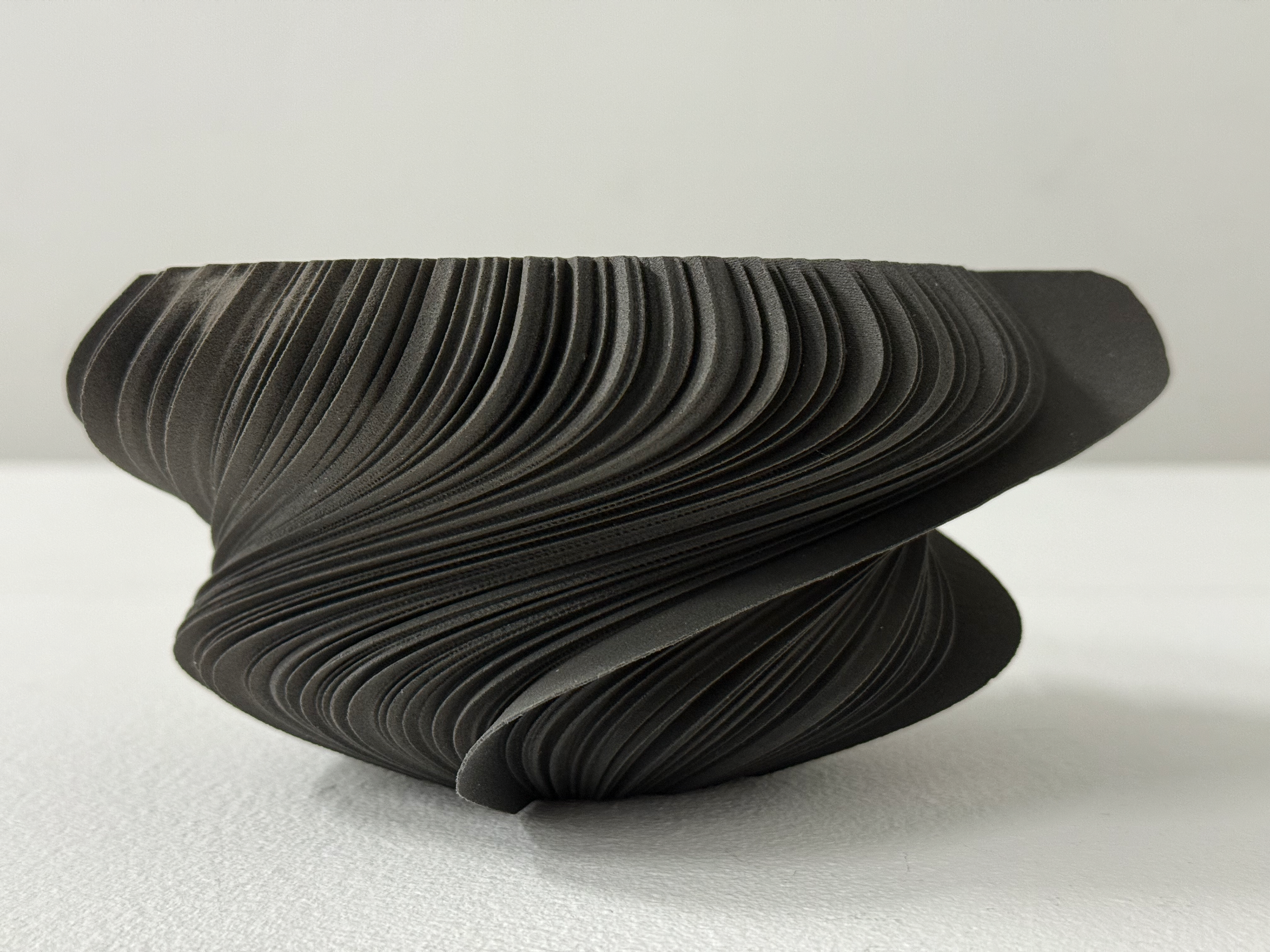
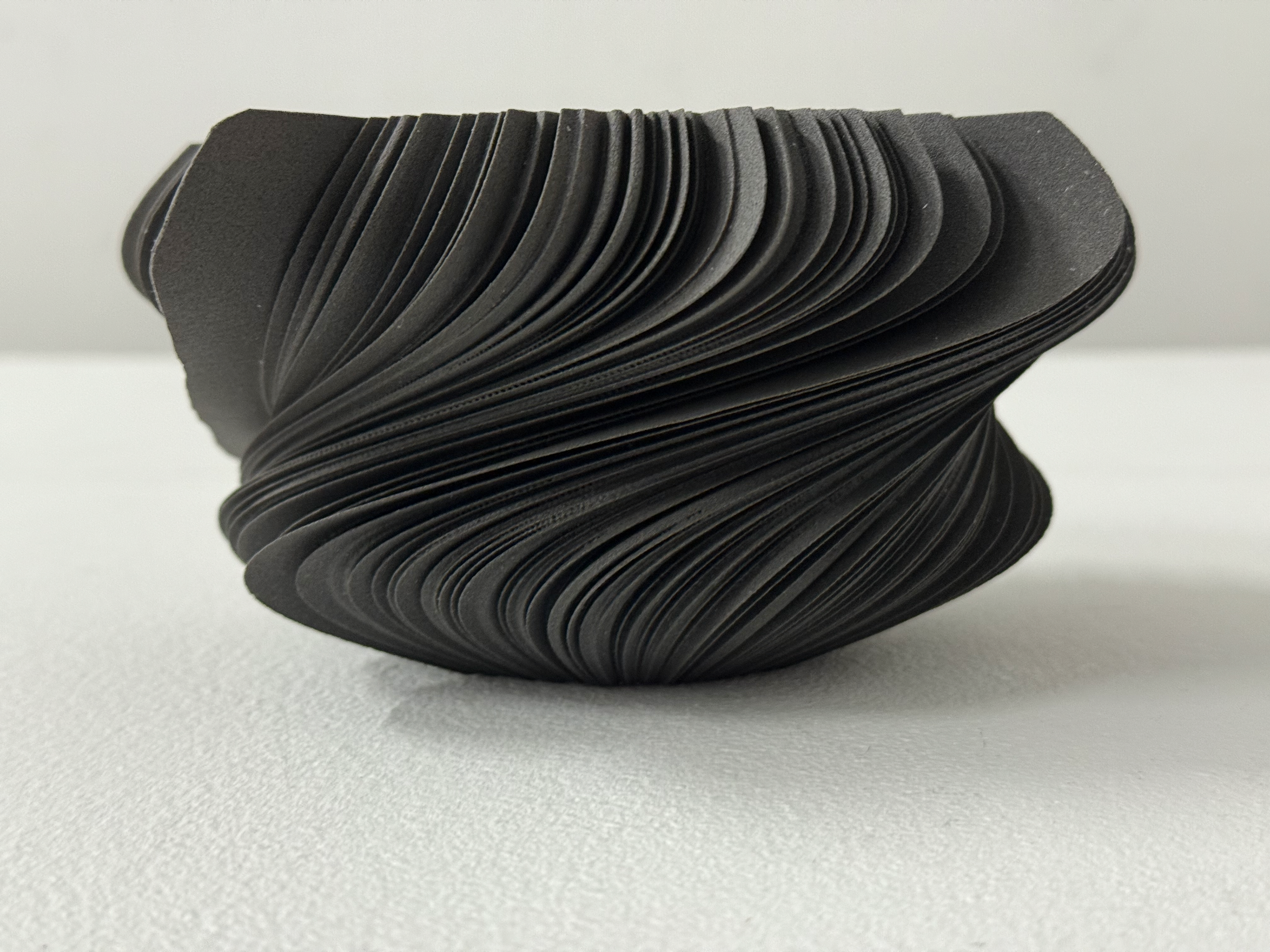
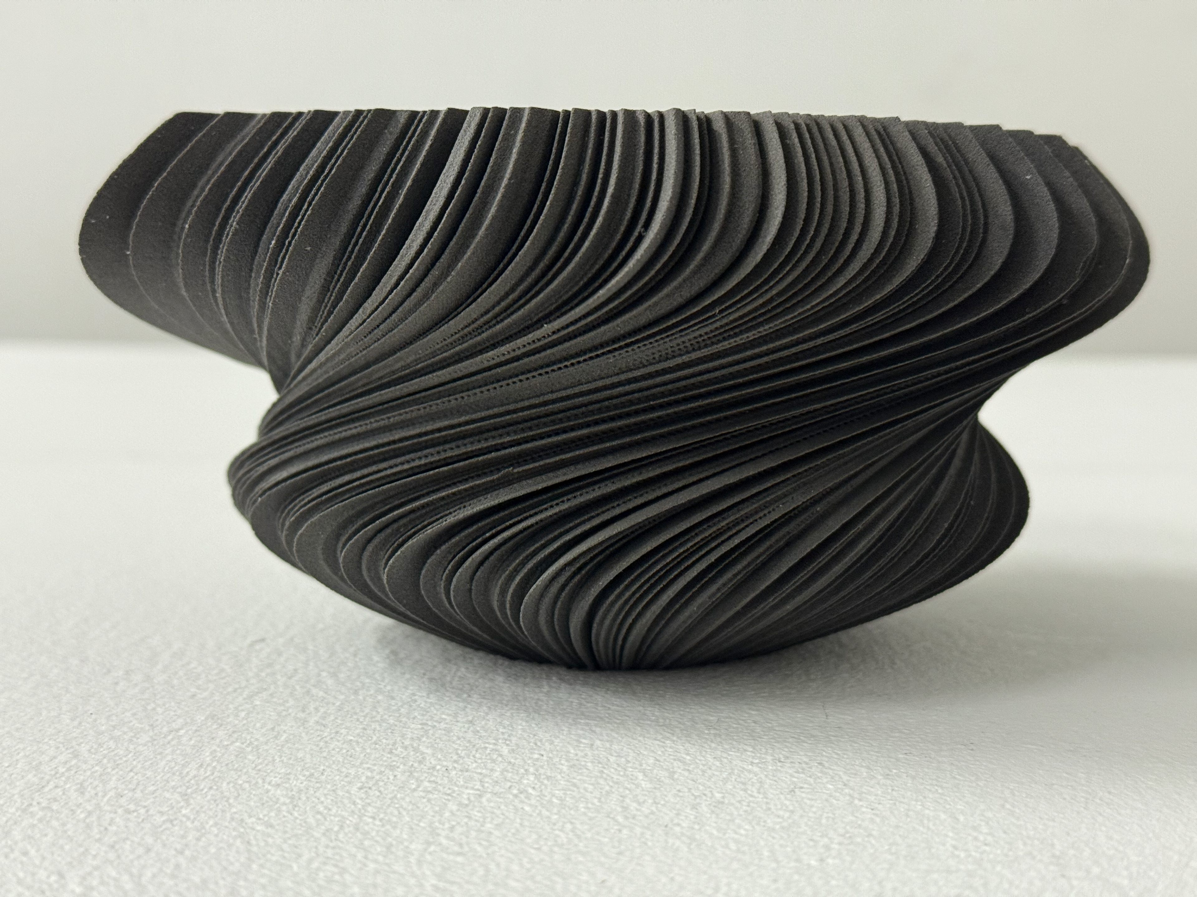
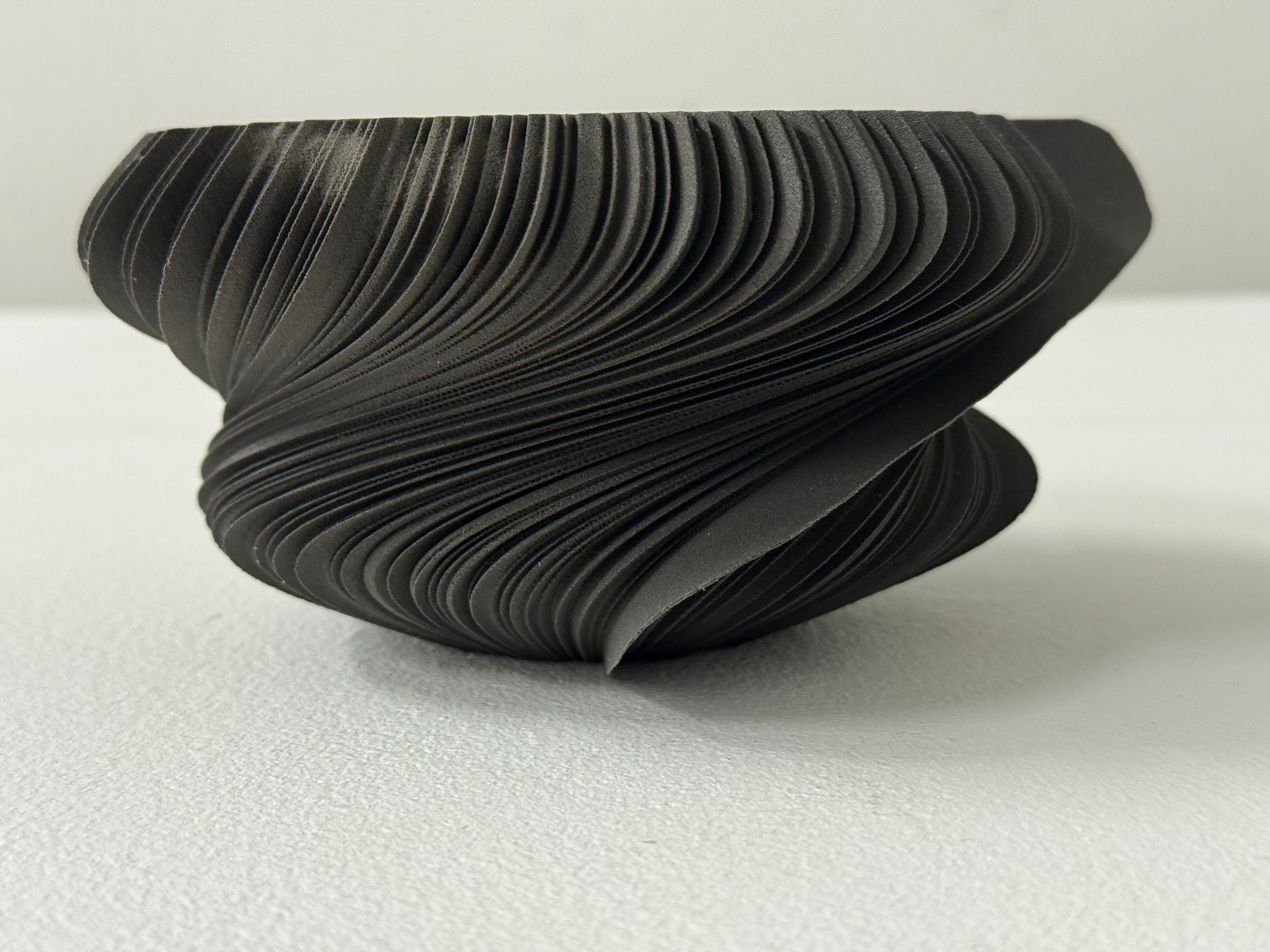
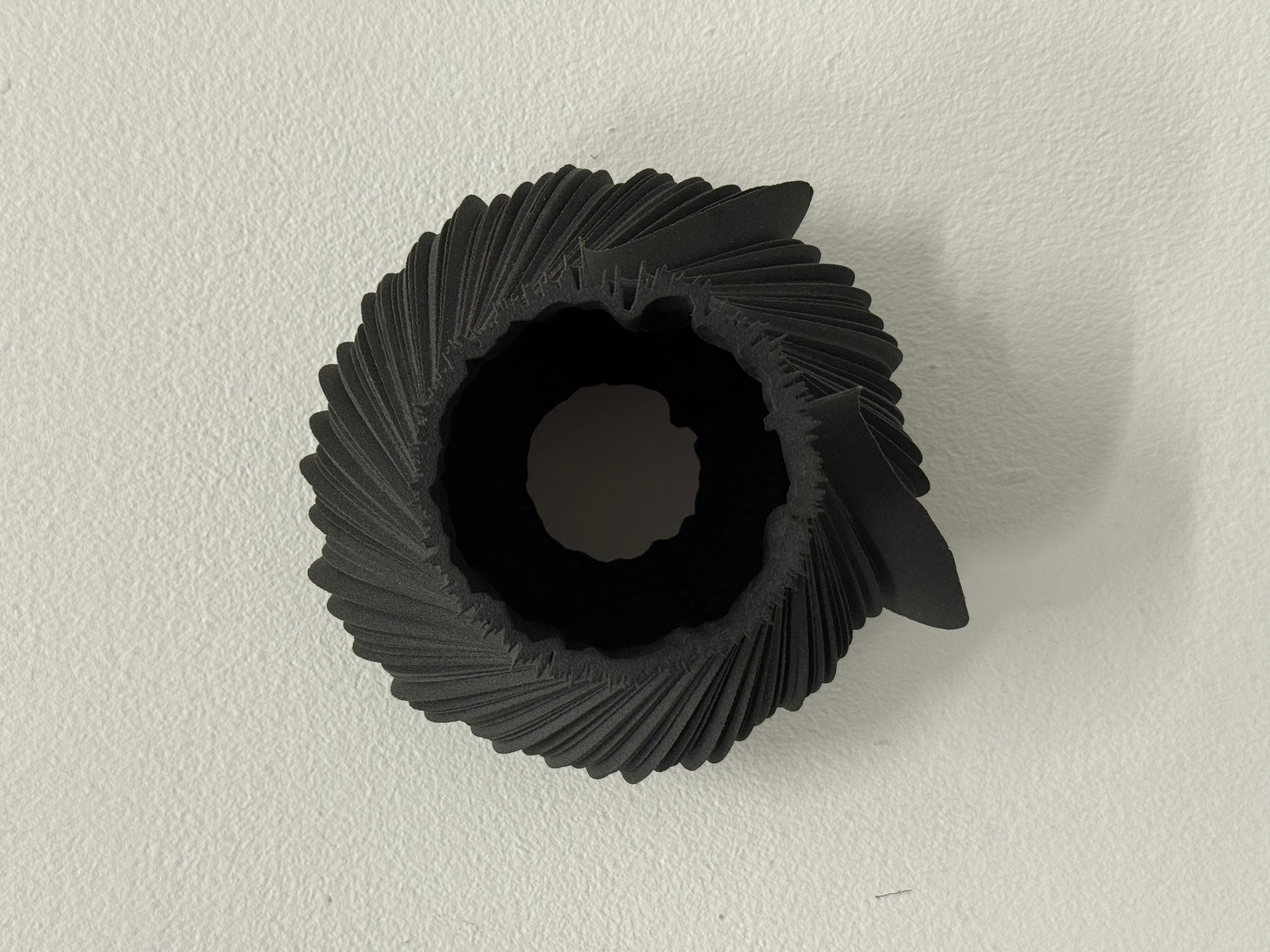
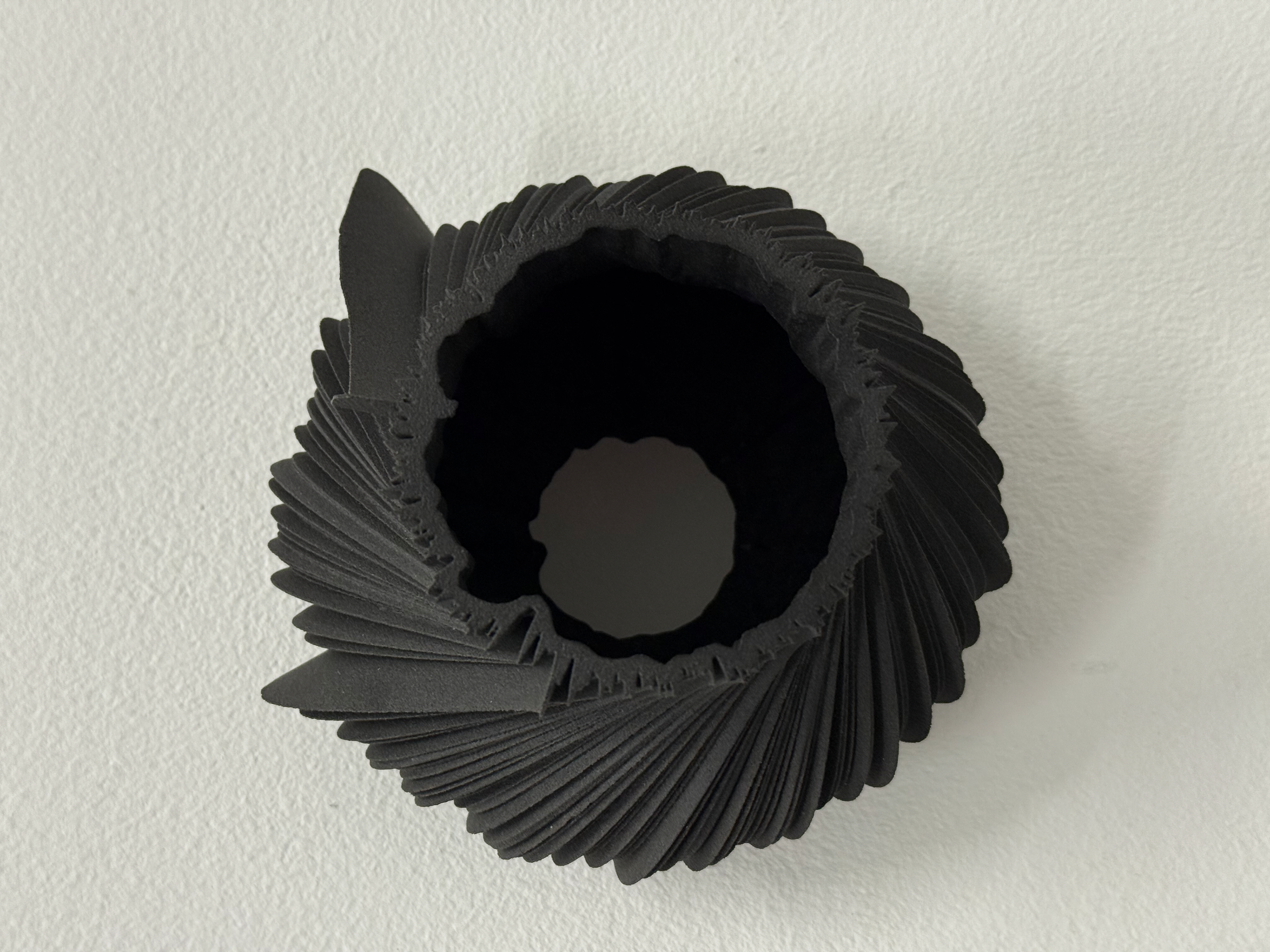
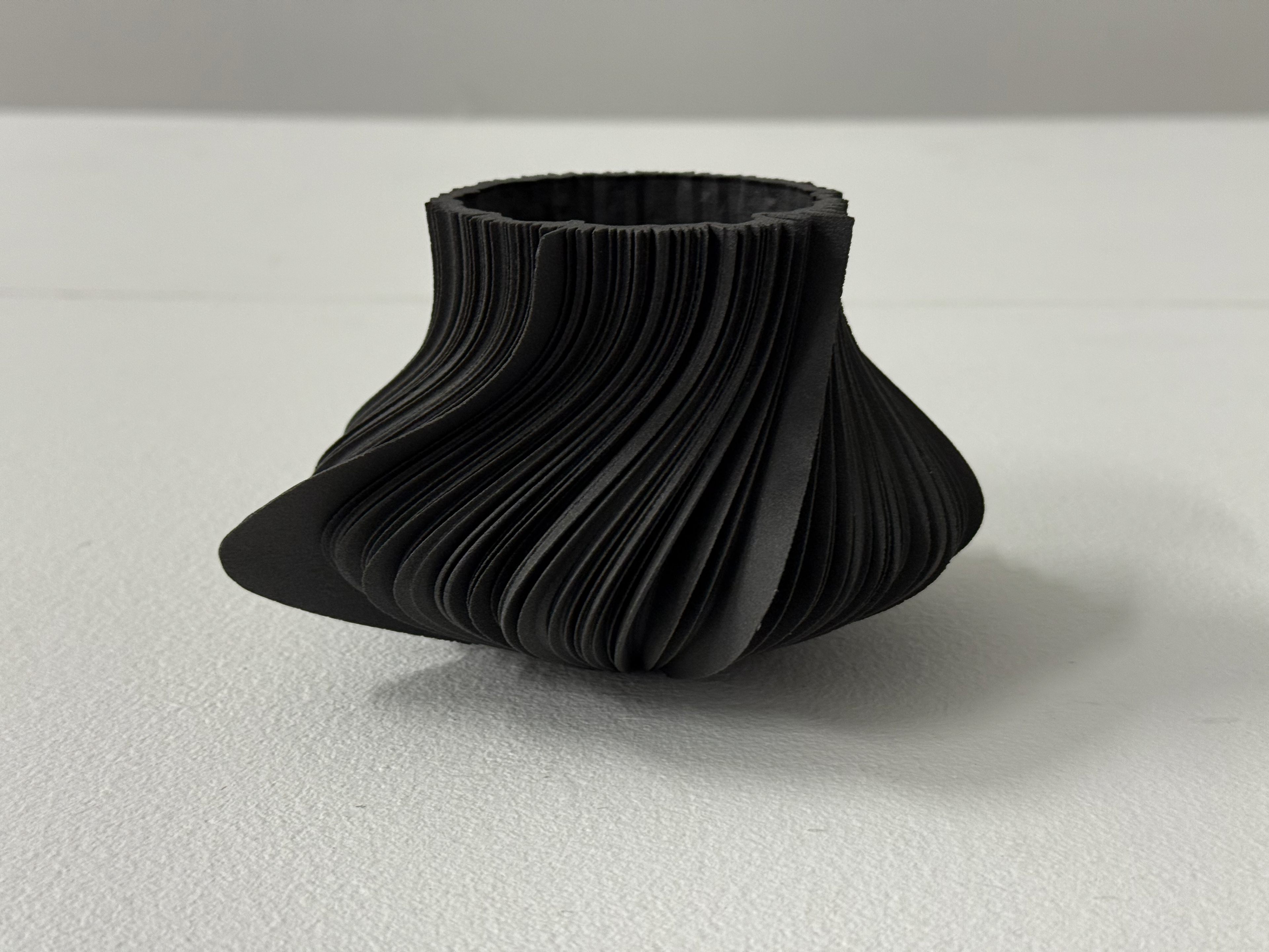
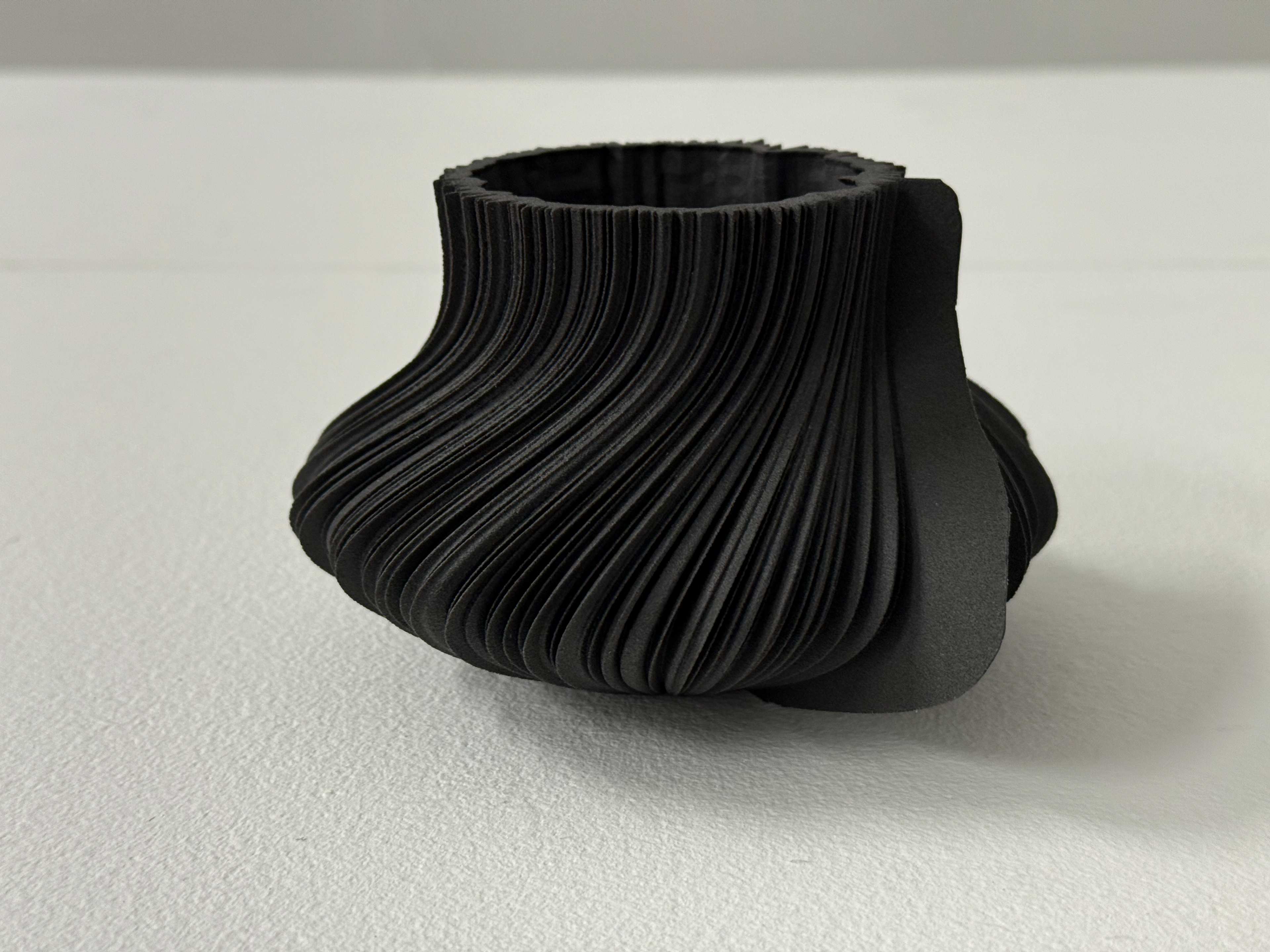
day 72
My best night's sleep.
Top view
View into the inside
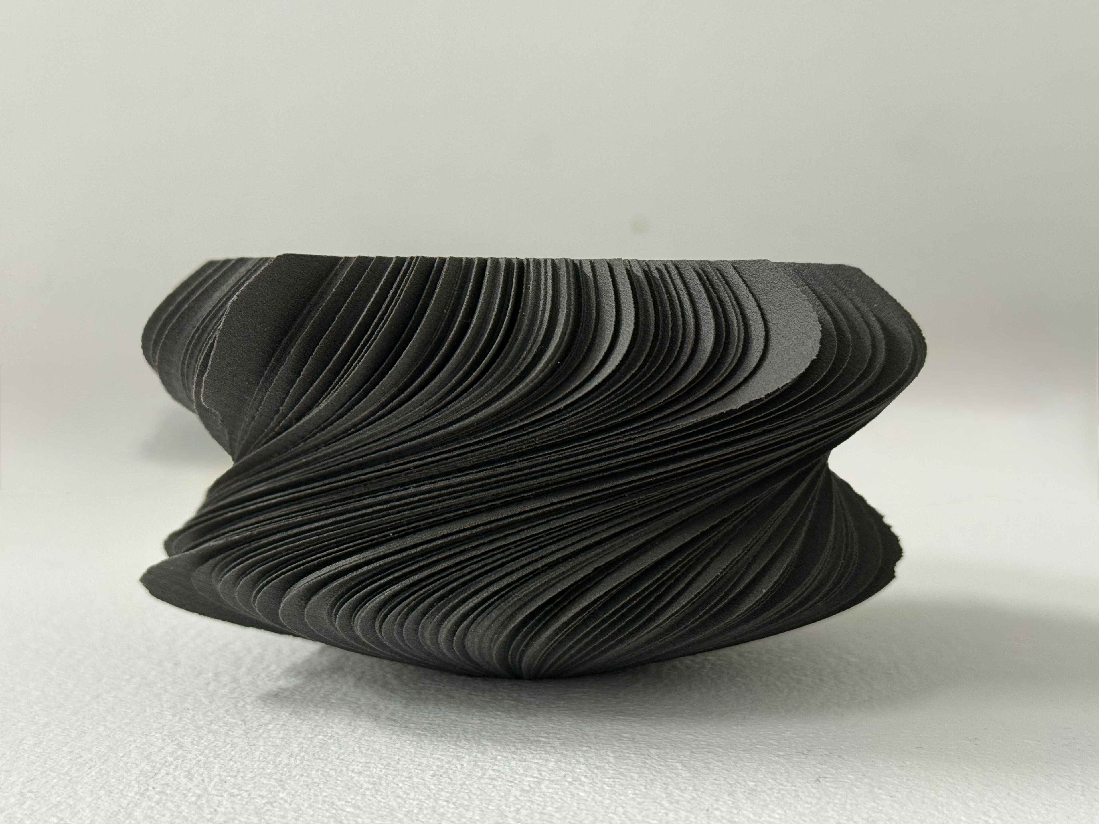
Side view
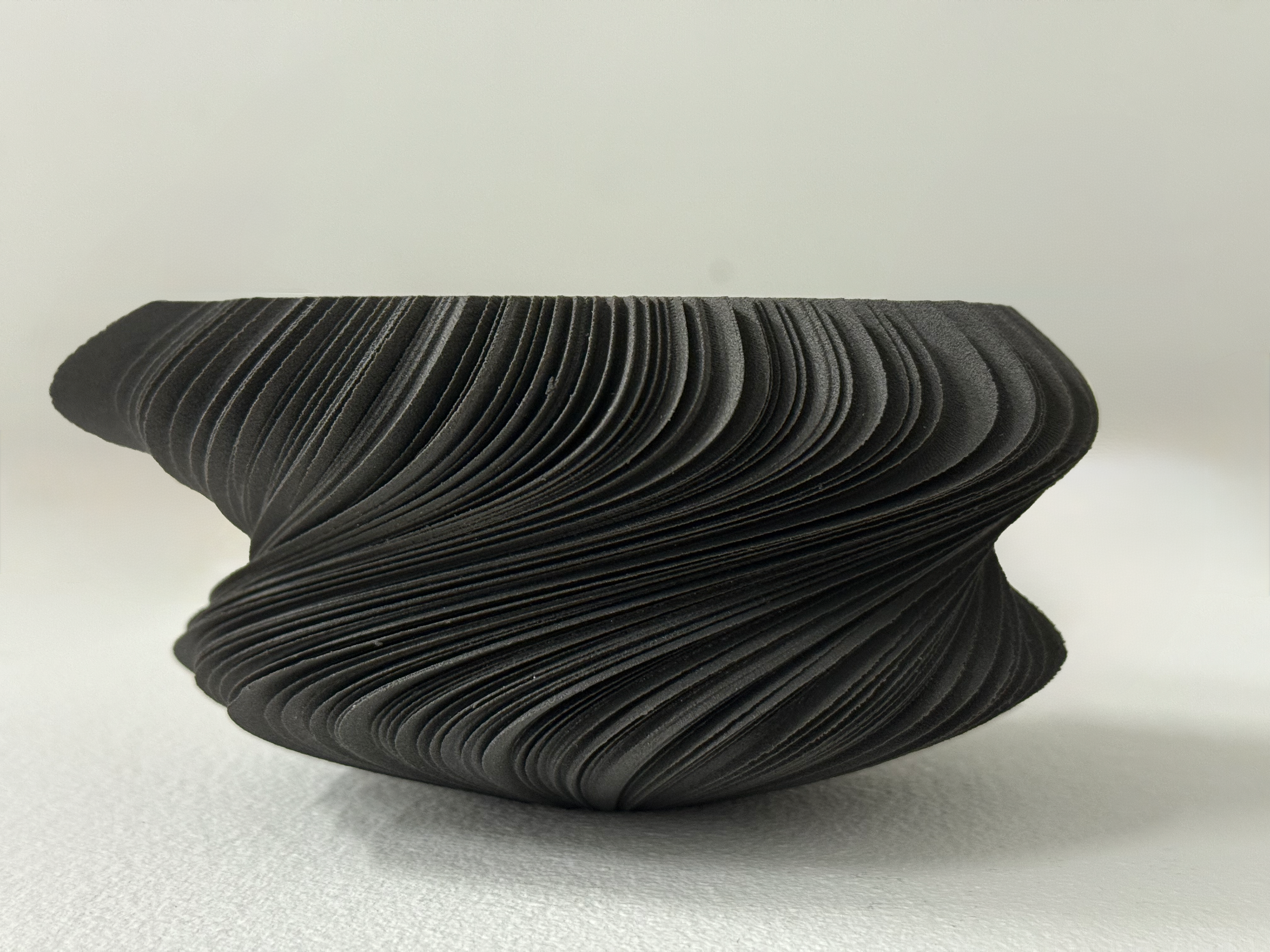
Side view
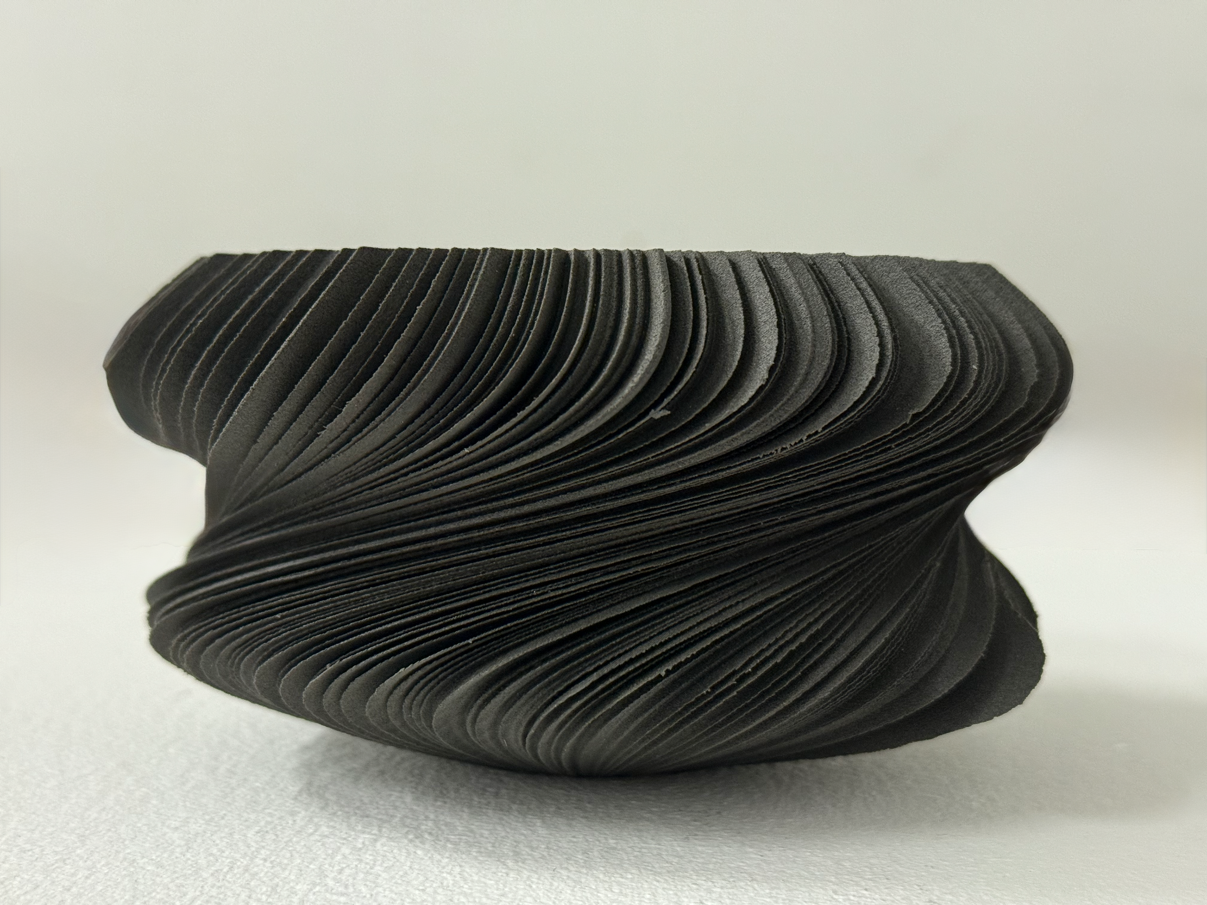
Side view
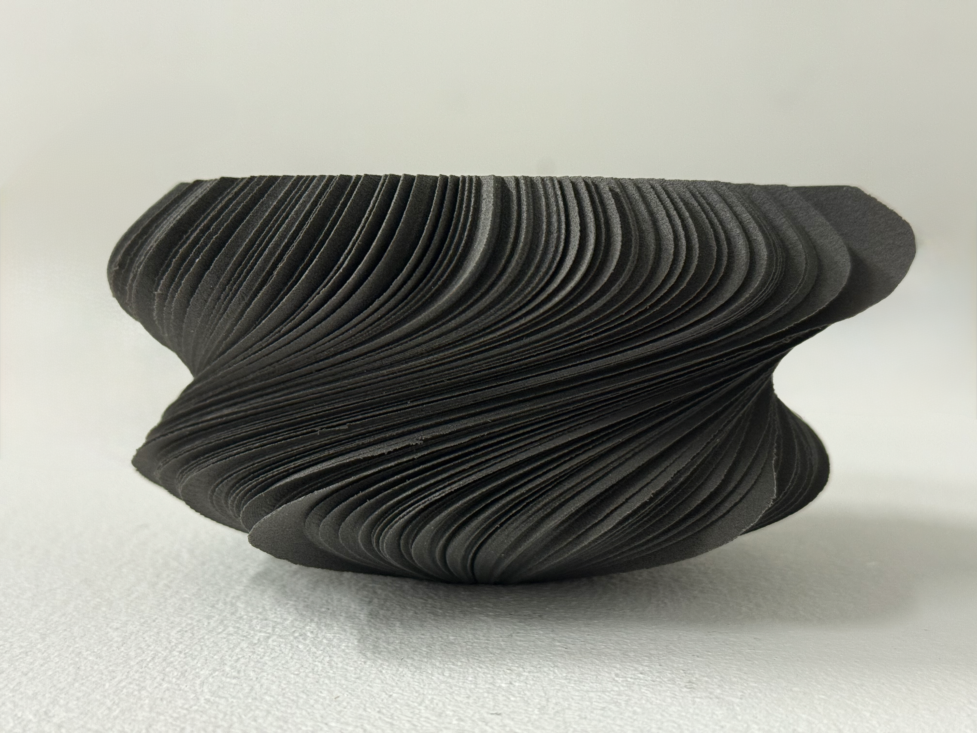
Side view
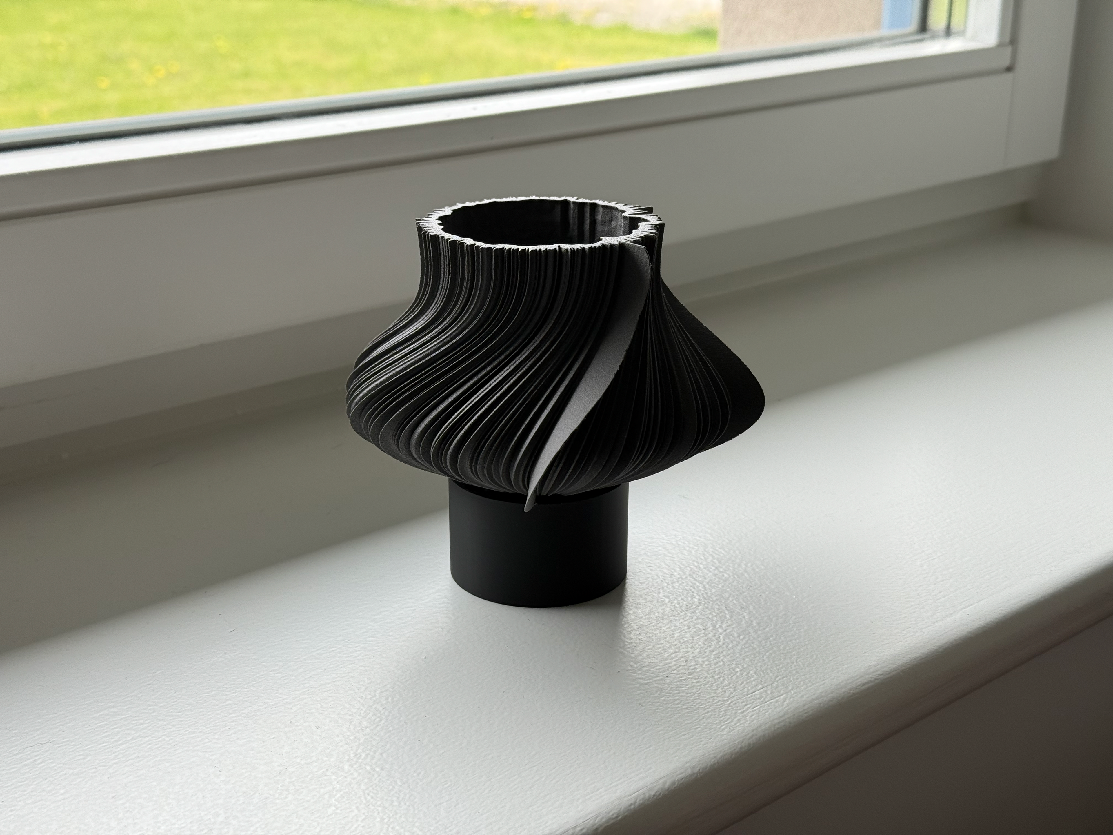
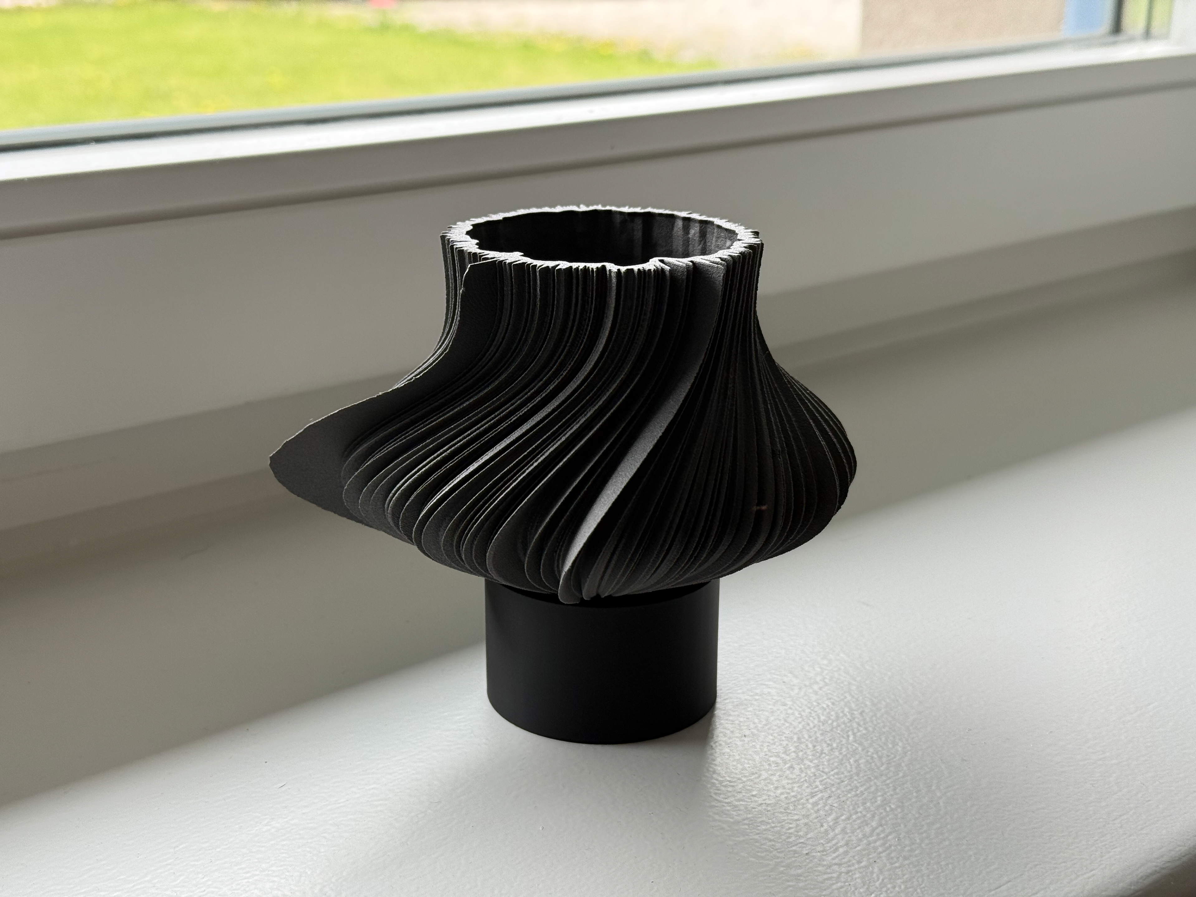
day 351
My worst night's sleep.
Top view
View into the inside
Side view
Side view
Side view
Side view
Whats in the box?
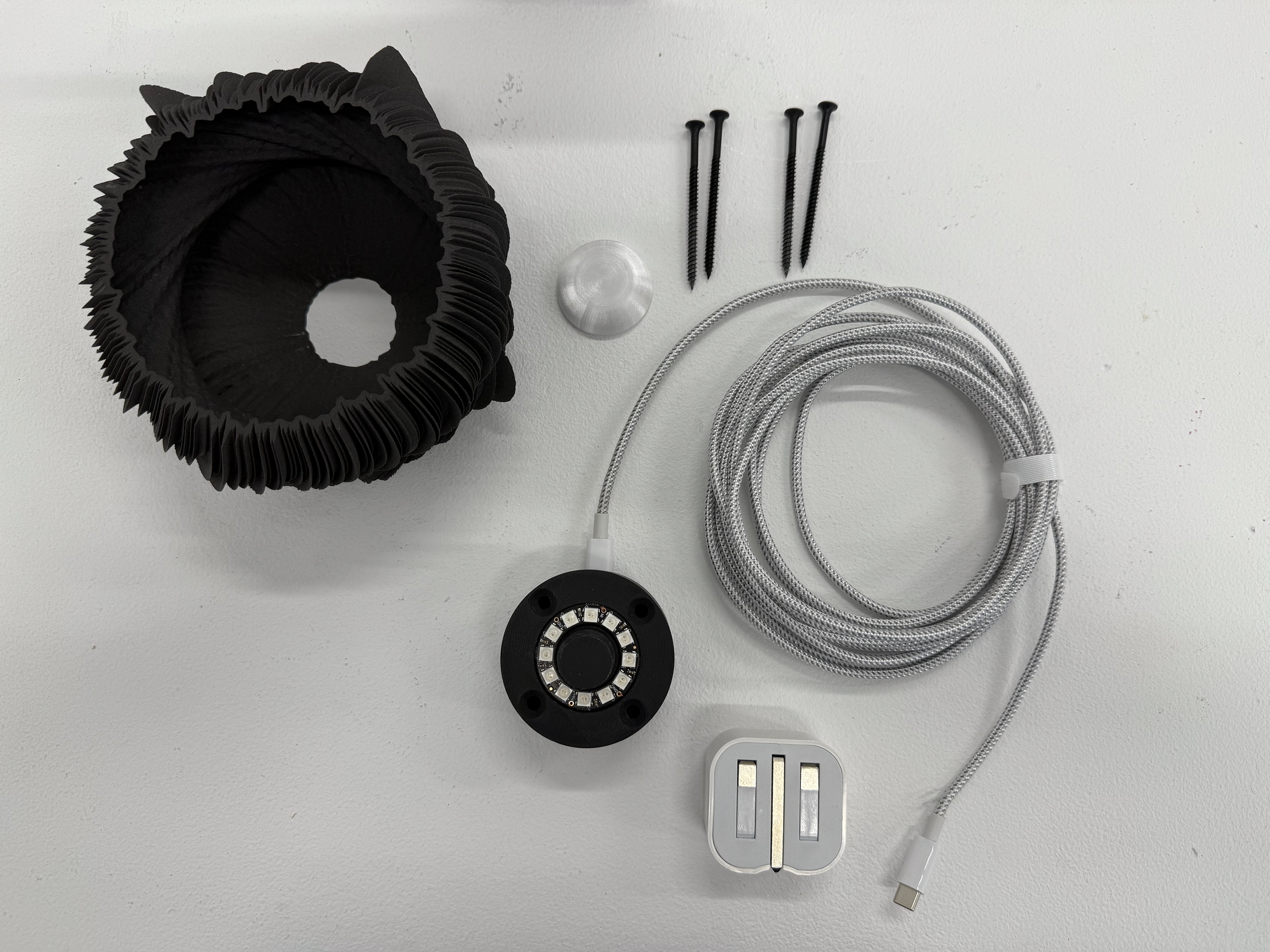
Everything that would included.
Mounting
Video of how to mount it's quite simple.
Complete
A walk around of the pieces after mounting and turning on.
Context Video
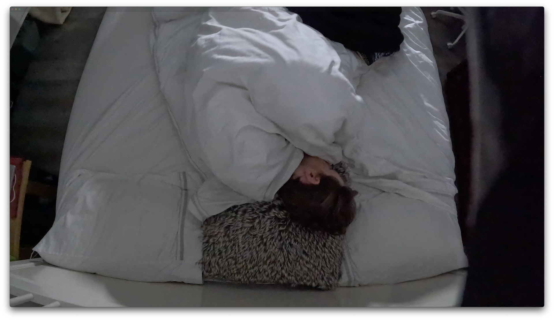
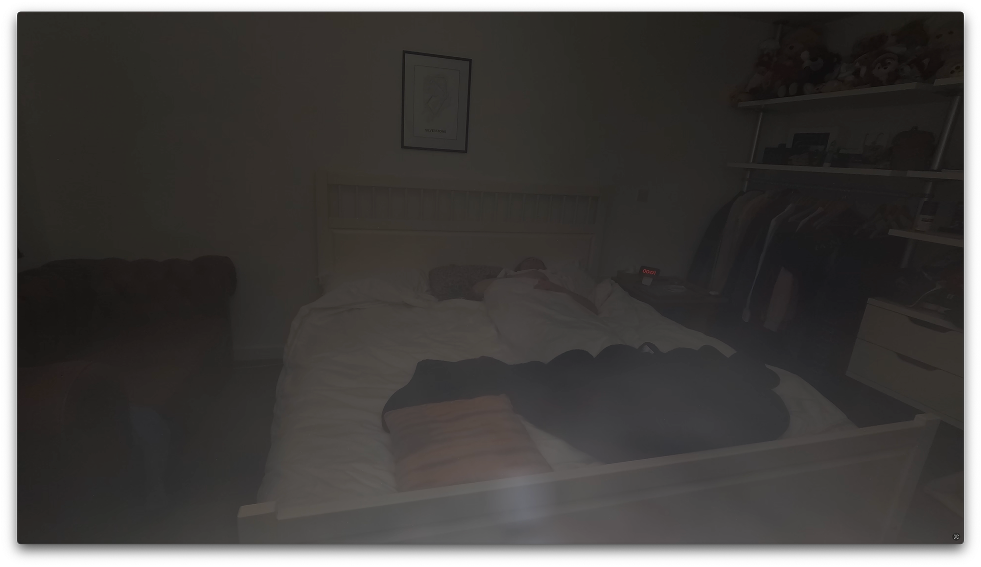
To make this video, I simply recorded my sleep by setting up a GoPro on top of my speaker and used a little light to illuminate in front of the lens because the room is pitch black even on camera. I shot using the GoPro's Nightlapse and setting it to take a frame every five seconds.
I recorded four different night sleeps, each time changing different factors. The first, I set up the GoPro over the top of my bed and slept with the light on, but the feedback was that it looked like I wasn't asleep and was unnatural. I also didn't like it because it was too revealing of how I move around during my sleep. For the rest of the setups, I used the GoPro's tripod and set it up on top of my speaker. In the second setup, I had no lights on and increased the exposure and decreased shutter speed to try and make sure I could be seen, but that didn't work as my room is pitch black. The third time, I slept with the blind open, which had the same issue until dawn when light finally came into the room. I also turned on "StandBy" on my phone to constantly display the time. The final time, I kept the "StandBy" mode on and used a small light to illuminate the lens, which allowed the GoPro to capture my room and my sleep. It was the final sleep that I used for the context film.
Setup for sleep 1
Sleep 1

Sleep 2
Sleep 3
Sleep 4
Artist Statement
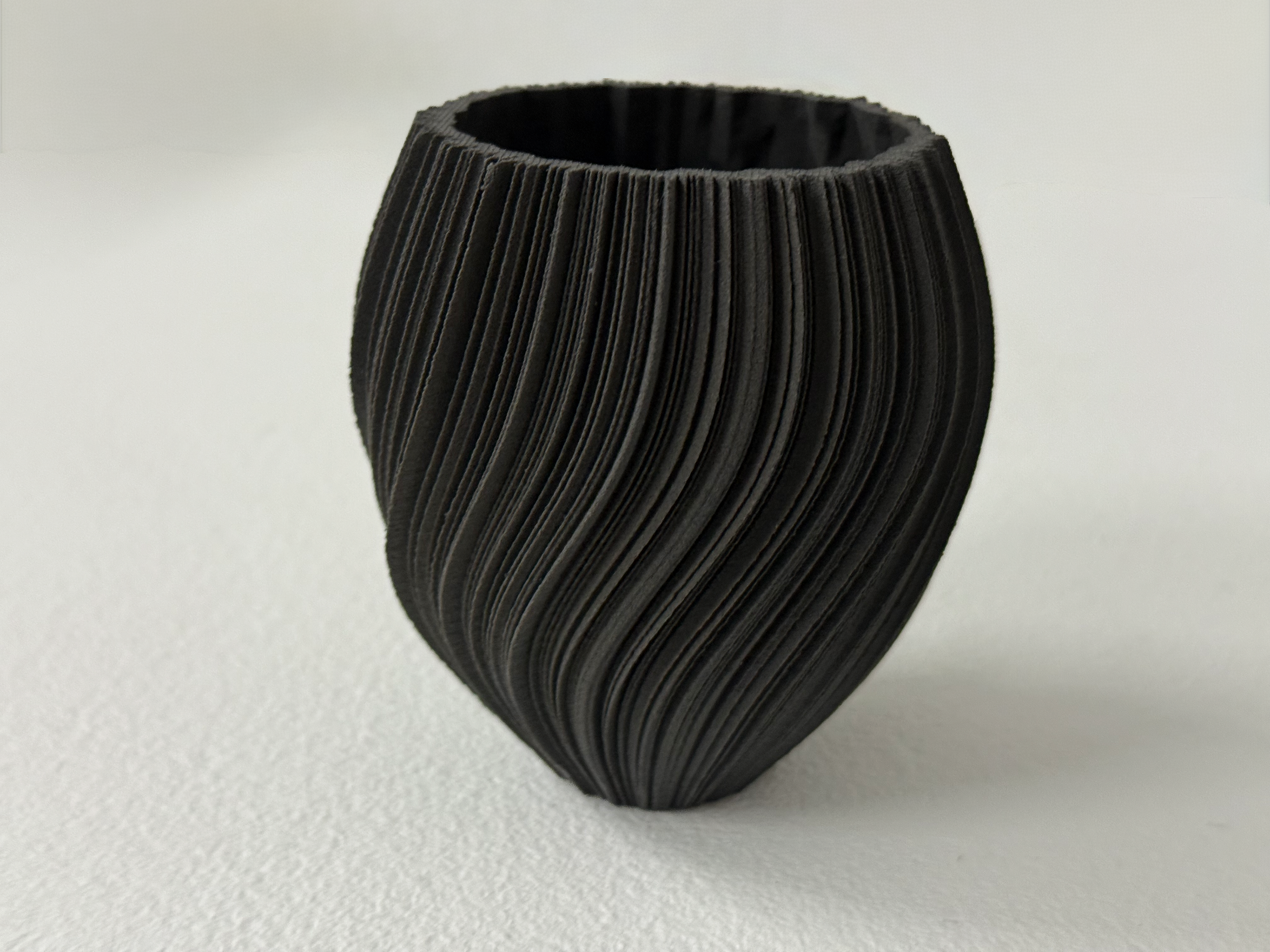
Sleep Symphony is a collection of pieces that visually represent sleep data. Each piece includes the duration of Deep, REM, Light, and Awake sleep, as well as sleep efficiency and performance, with the outline derived from the average heart rate over the dataset. This work creates visual and physical representations that bridge the gap between the abstract digital world and something people can actually connect with.
By incorporating a light into the pieces, they serve as night lights, encouraging daily interaction before and after sleep, prompting reflection on sleep patterns.
Sleep Symphony features data from two individuals: myself and my cousin, a professional athlete. By using two different people, I am bringing real-world contexts into the pieces, really showing how unique sleep is from person to person and illustrating the differences between an athlete and a non-athlete.
critical reflection
The question that initiated this project was simple: How can we make data interesting? But as the project evolved, that question started to have a focus - how can we visualise sleep data? Finding a solid data point to work with was key, and that’s what really shaped the project.
Coming up with a unique concept, especially under time pressure, isn’t easy. But then the idea to use my Whoop data just kind of fell into place. It felt natural and gave me something personal to work with, which made the whole process more engaging.
Moving from the WASP App to Fusion 360 completely transformed my workflow. It opened up so much more freedom, letting me create bigger, more interesting pieces. Initially, I was going to print in clay since I was already using the WASP App, but with the switch to Fusion 360, I was keen to explore a new material I hadn’t previously worked with. It opens up options for future projects, like expanding into Multi Jet Fusion (MJF) printing and exploring other materials within that technology. Experimenting with TPU was another standout part of the project. It was fascinating to see how the material reacted in different scenarios, and it helped me understand where and how I could use it effectively in the future.
I started this project wanting to figure out how raw data could be turned into something tangible and accessible. I aimed to create visual and physical representations that bridge the gap between the abstract digital world and something people can actually connect with. Looking back, I think I’ve done exactly that. But I also went a step further, bringing real-world contexts into the pieces, which really showed how unique sleep is from person to person.
I’d love to take this idea further, but doing it on my own is tough, especially because accessing raw data usually requires formal requests. A logical next step would be to collaborate with a company that provides devices like Whoop to their clients or employees, or even work directly with Whoop. In that setup, I’d be contracted to create forms based on specific data they want visualised.
There’s still room for refinement. I’d need to rethink the mounting and lighting solutions. Ideally, I’d design a custom LED ring for each object, with a built-in controller and a USB-C connection to allow for a sleeker overall design. I’d also revisit using resin for the lenses, frosting or clouding them to get a different effect. These changes would affect the mount’s size, so that would need further development. I might even explore different materials for the mounts, something stronger than PLA. For the nylon, I would change it but I’d look into MJF printing and other material possibilities.
Overall, this has been my strongest project and for the first time, I’m genuinely happy with how it turned out. I’m proud of the work I’ve done, and in a world overflowing with data, I think this brings a fresh, unique perspective.